DRV10964: Maxon EC 9.2 starts for a few steps but stops and goes to lock

Part Number: DRV10964

Motor to drive: maxon ec 9.2 10mm blushless https://www.maxongroup.com/maxon/view/product/624162

Values at nominal voltage
Nominal voltage 4.5 V
No load speed 13900 rpm
No load current 34.7 mA
Nominal speed 3620 rpm
Nominal torque (max. continuous torque) 0.702 mNm
Nominal current (max. continuous current) 0.27 A
Stall torque 1.01 mNm
Stall current 0.364 A
Max. efficiency 50 %
Characteristics
Terminal resistance 12.4 Ω
Terminal inductance 0.281 mH
Torque constant 2.79 mNm/A
Speed constant 3450 rpm/V
Speed / torque gradient 15400 rpm/mNm
Mechanical time constant 38.2 ms
Rotor inertia 0.237 gcm²
Other specifications
Number of pole pairs 4
Number of phases 3

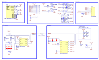
The design we came up with was:

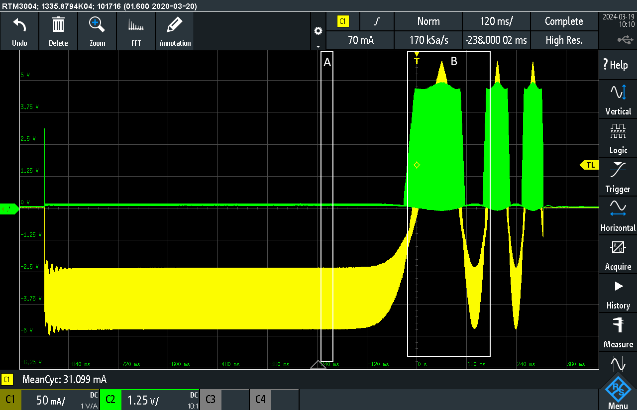
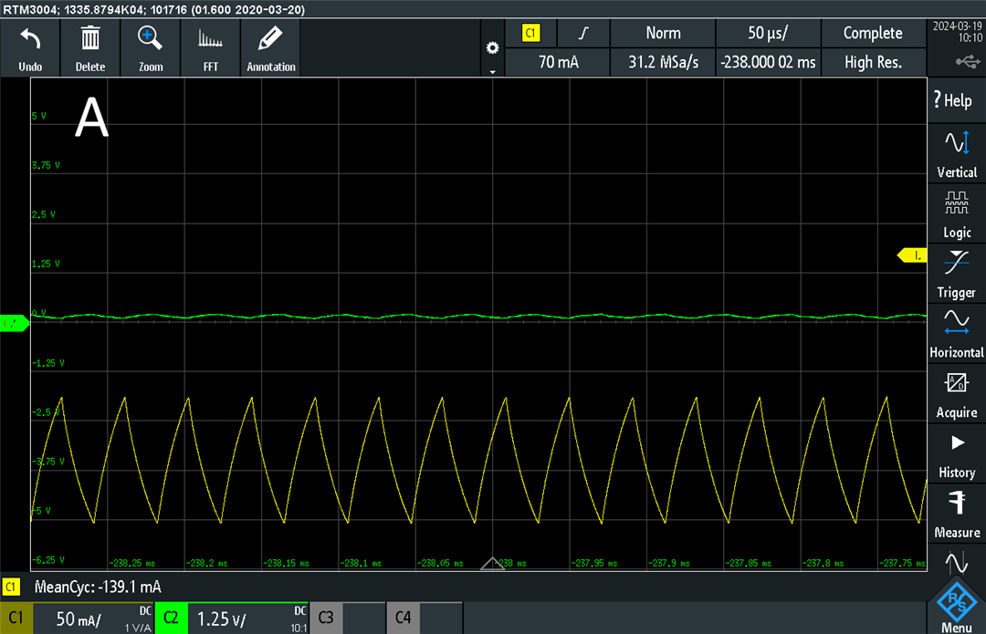
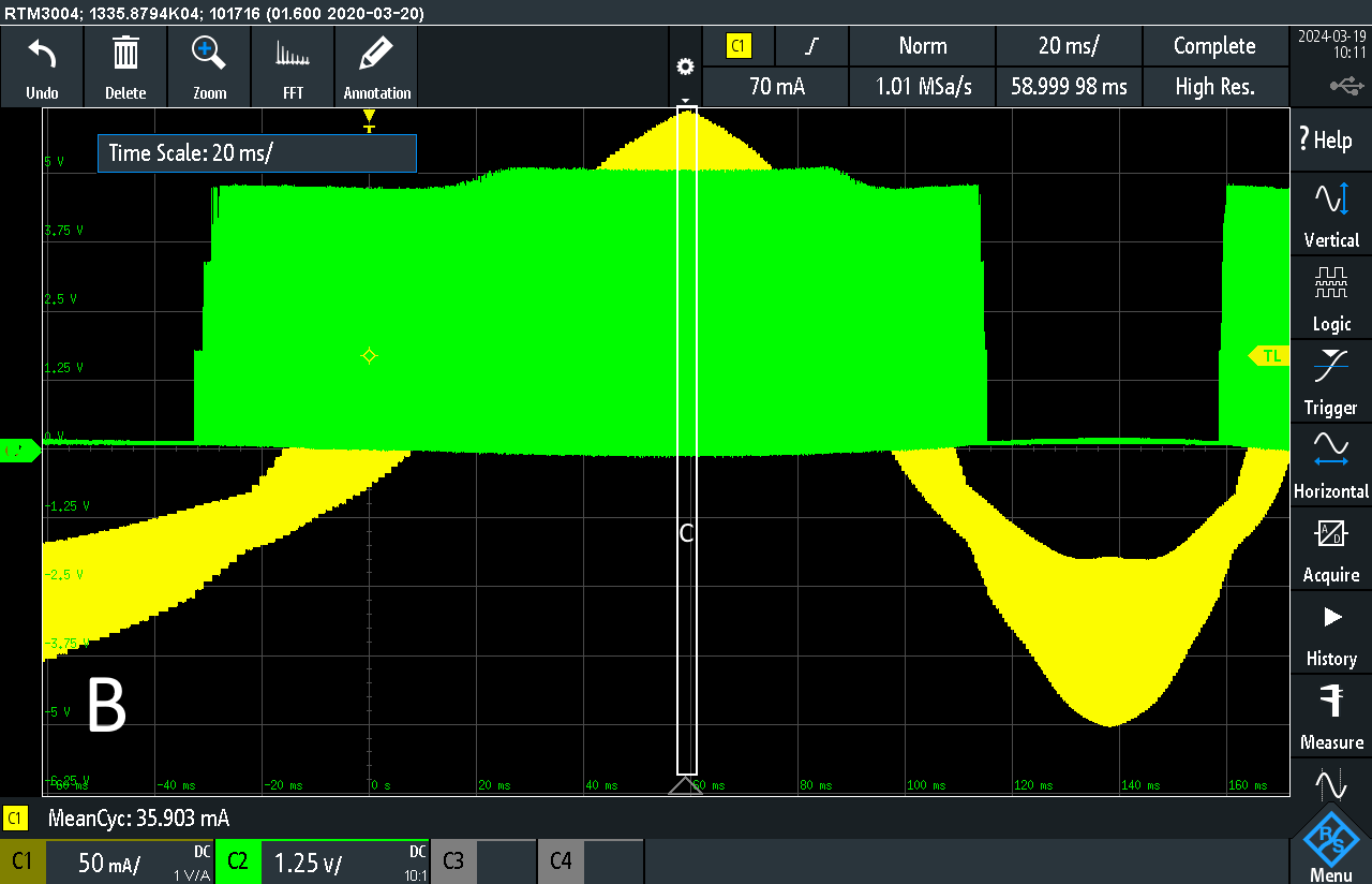
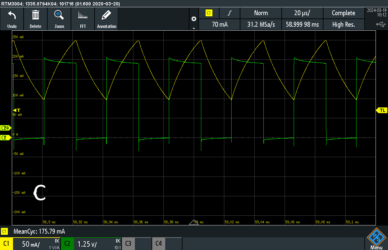
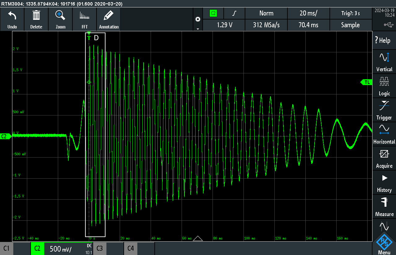
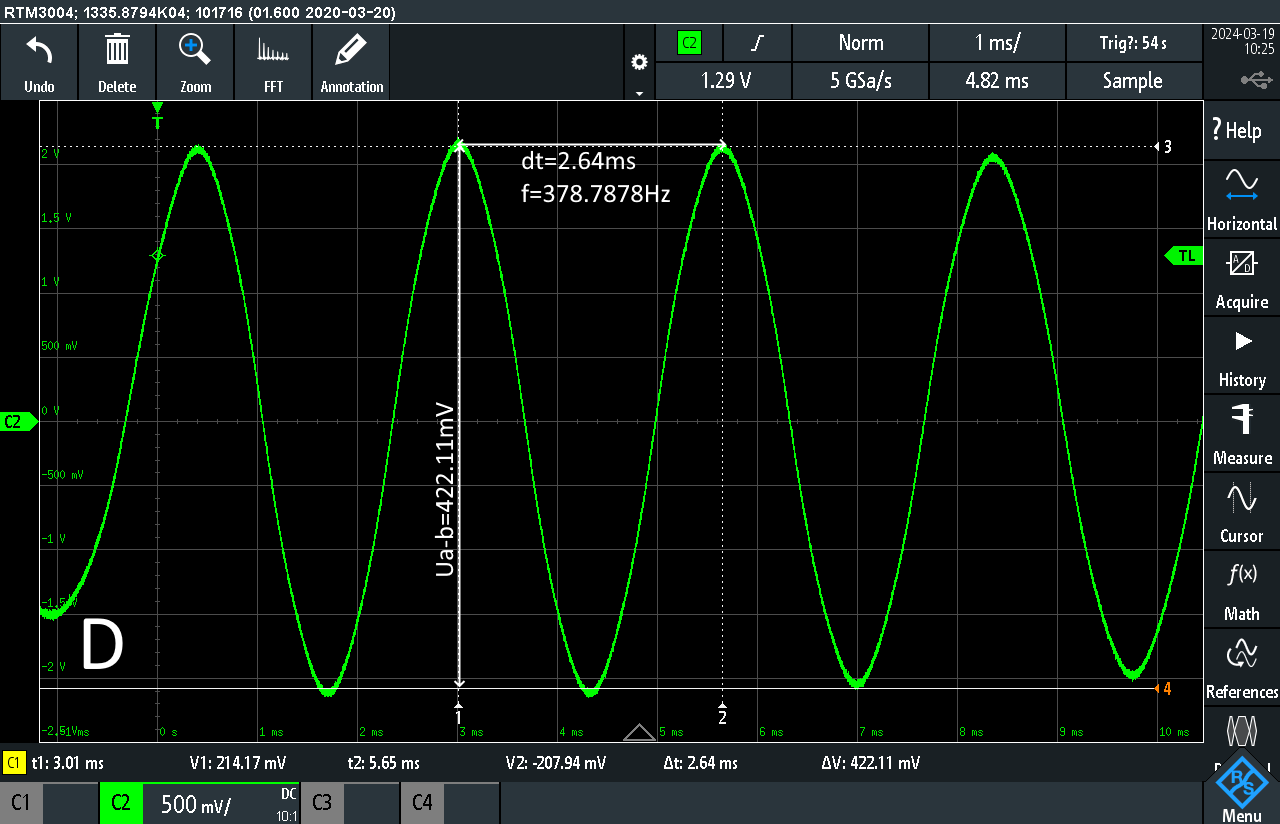
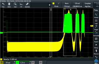
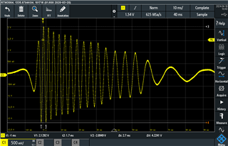
In my tests, the motor aligned, made a few steps and then it looks like it goes to a lock condition:

I tested also to replace the LEDs parallel to the windings (H101, H103, H104) with resistors (the 2k2 were replaced with 0 Ohm) of 24 ohms to draw at least a current of 100mA to not fall into the "no motor" lock. No success.

I also tested to set the CONFIG-Voltage to 0V and to VCC also with no success. The result is always the same as in the video....

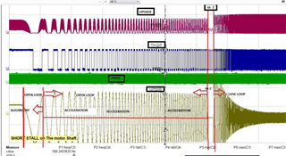
By the timing, i would say, it falls into a lock but i dont knwo how to figure out which one and how to mitigate it....

any ideas are very appreciated

Thanks!

-Tom

  • Ah... The Switch S100 is shorted, so the PWM always gets to the DRV10964 .... ;)

  • Hi Thomas, 

    Thanks for posting to the e2e motor drivers forum. 

    Our team expert on this device is out of office for a week, so responses to this debug thread will be delayed until he returns next week.

    Please give us some additional time to address your questions/concerns, and feel free to add further information to the thread in the meantime if you believe it will help the debug effort. 

    Best Regards, 
    Andrew 

  • No Problem. It is not super urgent. :)

  • Thank you Thomas

    Best Regards, 
    Andrew 

  • Hi Thomas,

    Thanks for waiting for a week.

    Looking at the motor Kt and speed (aprox 1000Hz) the hand off speed looks very small (12.5Hz)

    For better reliable hand off please try for above 100Hz.

    Can you confirm your settings?

    Thanks and Best Regards,

    Venkatadri S

  • Hi Venkatadri,

    As written in my initial post, i also tried a CONFIG-Voltage of 0V and VCC which equales a setting of 87.5Hz and 187.5Hz respectively. So as already written i already tried the handoff-speed above 100Hz (187.5Hz).

    I dont know which settings you refer to i can confirm otherwhise. I posted the schematic. Everything else in terms of configuration is there already and documented... Like the PWM of around 40kHz...

    The behaviour can be seen in the video.

    Thanks and best regards,
    Thomas

  • Hi Thomas,

    Thanks for providing details. I will reply to you by this week end.

    Thanks and Best Regards,

    Venkatadri S

  • And? Someone has an idea why this Motor goes to lock?
    It looks like this driver was made for such motors and the setup was done to the best of my knowledge and i also tested Min-PWM to max-PWM and from min Handoff-f to max Handoff--f, tested the load increase to not fall in the "no motor"-Lock, all without success.... Motor goes always to lock after (successfull?) alignment and a few (slow) steps.

  • Hi Thomas,

    I haven't got chance to verify the motor details which you have shared. I request another day time, I will reply.

    Thanks and Best Regards,

    Venkatadri S

  • HI Thomas,

    Another time same check about Hand off speed. Your video is not working, can you send me scope waveform.

    I don't see any reason for this motor not able to spin.

    Can you use voltage probe and oscilloscope and probe on OUTA and the phase A current if possible.

    We want to see BEMF at the hand off point like shown below

    I see torque constant data is available. In order to re check can you try measuring kt of the motor like mentioned below

    Using oscilloscope voltage probe across two phases. Spin rotor by hand , measure peak to peak voltage of adjacent peaks and time between adjacent peak?

    Can you post CRO waveform here?

    Thanks and Best Regards,

    Venkatadri S

  • Hi Venkandri

    For me, the video only wotks in Chrome...

    Yes: I can see to scope the motor on tuesday

    I will scope the OUTA with voltage and Current (Via Hallsensor).

    I will try to measure the kt of the motor as instructed.

    Best regards and already: Thank you for helping! Slight smile

    Thomas

  • Okay. i measured as you ordered.

    Yellow = Current on Coil a
    Green = Voltage on Coil a

    the first (longer part) is the alignment and then the few (slow) steps follow. After those steps, it goes to lock as it seems.

    The Details A and B:

    The details of C:

    For the kt:

    Details of D:

    So a voltage of around 422mV at around 379Hz betwheen 2 coils while i spun it by hand.

  • Hi Thomas

    Thanks for sharing the image. I will look at it and reply to you.

    Thanks and Best Regards,

    Venkatadri S

  • Hi Thomas,

    In the last image please correct me what I am reading. If we look at Y scale it is Peak to Peak as aprox 4V  (your comment as 422mV looks not proper)

    If we take as per Y scale (Assuming voltage probe attenuation is properly configured) the BEMF constant = Peak to Peak / (2* SQRT(3) * Frequency)

    Then BEMF Aprox 3mV and we can also verify from the data sheet provided, 4.3mV/Hz as per Speed constant 3450 RPM/V (Take inverse of it and convert to V/Hz with Pole Pair data).

    Sorry for more debug, can you capture the current waveform at the hand off point? I want to see the frequency it reached? The motor phase current becomes zero once motor reaches the hand off speed and re sync after measuring Kt. 

    Thanks and Best Regards,

    Venkatadri S

  • Hi Venkatadri

    Thanks for your reply.

    In the last image please correct me what I am reading. If we look at Y scale it is Peak to Peak as aprox 4V  (your comment as 422mV looks not proper)

    You are right. I placed 2 cursors on the peaks and dV=422 is shown in the DSO betwheen the cursors #3 and #4. But yes: by the scale, it should be around 4ish volts.
    Hm! I'll measure it again and check if i accidently switched the probes 10:1 / 1:1
    However, this will take a bit of time as i just started my sports-sabbatical and many international competitions on my hunt for olympic places just started....

    Sorry for more debug, can you capture the current waveform at the hand off point?

    I dont think so, as there is no handoff-Point as the motor never really spins and goes to lock-condition, right? How do i find this handoff-Point? (Sorry, i think i dont really understand the theory of the handoff-point...)
    Can you mark this handoff-Point in the first image in my Previous post?

  • Hi Thomas,

    Good luck to your competition. 

    The hand off point looks like shown in the data sheet page #19 DRV10964 5-V, Three-Phase Sinusoidal Sensorless BLDC Motor Driver datasheet (ti.com)

    If motor never starts spinning then some other issue.

    Initially motor start spinning in open loop, after the motor speed reaches configured hand off speed device stops divining briefly, during that moment phase voltage will be of BEMF, device measures this BEMF and calculated Kt of the device.

    Thanks and Best Regards,

    Venkatadri S

  • Hi Venkatadri

    The hand off point looks like shown in the data sheet page #19

    I think my point doesnt get understood:
    - The scope i posted is ALL thats happening:

    - There is NO HANDOFF POINT reached before it seems to go in Lock
    - The Graph on Page 19 as you told, shows a waveform which HAS a handoff-Point (Change from open- to closed loop):

    This does NOT happen with me. It doesnt even reach this point. Doesnt come close. 3 steps on this one coil and lock. Page 19 shows like 50-70 steps till handoff....

    As posted multiple times: The Motor gets aligned, The motor starts spinning for a FEW STEPS. See Video in first post.
    Then it goes to lock. See Video in first post.

    If motor never starts spinning then some other issue.

    The motor works. I tested it multiple times in our Insulin pump, with a weird chinese Drone-Motor-Controller and even with a Arduino-DIY-Solution... The motor works on everything except on a dedicated BLDC-Controller here...

    Initially motor start spinning in open loop, after the motor speed reaches configured hand off speed device stops divining briefly, during that moment phase voltage will be of BEMF, device measures this BEMF and calculated Kt of the device.

    As said, as posted, as shown in video: The Controler gives up accelerating the motor after 3 steps.

    So I try to explain it AGAIN:
    - Motor seems to align
    - Motor makes 3 steps on one coil
    - Motor goes to lock
    - There is no handoff reached in this 3 steps of the motor (like 3/4 turn or something like this. See Video)
    - Motor works as confirmed by driving it with multiple different DIY-Solutions

    BEMF:
    To the previous question: You are right. The cursors were of another channel with factor /10.

    So the BEMF = 370Hz and Upp 4.22V

  • Hi Thomas,

    I am out of office since week, I will go through your updates and reply to you by this week end.

    Thanks and Best Regards,

    Venkatadri S