This thread has been locked.

If you have a related question, please click the "Ask a related question" button in the top right corner. The newly created question will be automatically linked to this question.

DRV2605L-Q1: Not getting Haptic feedback: DRV2605L-Q1

Part Number: DRV2605L-Q1
Other Parts Discussed in Thread: DRV2605L

Hi,

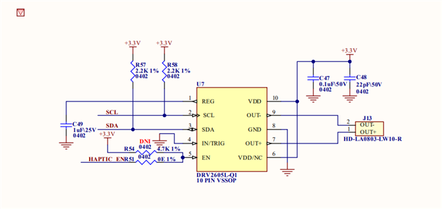
i have been working to generate Haptic feedback using DRV2605l-Q1, but not able to get the feedback. i have attached my code written according to the instructions provided in the device datasheet.

Please check it once and let me know what need to be done to get the haptic feedback. waiting for your swift support, now the project is in critical stage, please take it on priority.

Thanks,

Sumit.

#define DRV2605L_Q1_DEVICE_ADDR             0x5A

/*uint8_t MODE_reg[2];
struct RegAdd_Data {
    uint8_t Reg_Add;
    uint8_t Data;
};*/

//struct RegAdd_Data InitBuf[]{
uint8_t Mode[2] = {0x01,0x01}; /*Mode selection and Standby clear*/
uint8_t Lib_Select[2] = {0x03,0x02}; /*Selecting library TS2200 Library B*/
uint8_t Feedback_Ctrl[2] = {0x1A,0xA8}; /*Feedback Control*/
uint8_t R_Volt[2] = {0x16,0x8E}; /*Rated voltage for closed loop ERM*/
uint8_t OD_Clamp[2] = {0x17,0x8C}; /*OD_Clamp for closed loop ERM*/
uint8_t Auto_calib_Time[2] = {0x1E,0x30}; /*Auto calibration time*/
uint8_t Drive_time[2] = {0x1B,0x1F}; /*Drive time*/
uint8_t SamBlanIDISS_Time[2] = {0x1C,0x35}; /*Sample, Blanking and IDISS time*/
uint8_t GO_Bit[2] = {0x0C,0x01};  /*GO Bit*/

uint8_t InitDataLength = 2;

uint8_t Mode_PWM[2] = {0x01,0x03}; /*Mode selection and Standby set*/
uint8_t Analog_Input[2] = {0x1D,0x02}; /*Control register 3*/

uint8_t Mode_RTP[2] = {0x01,0x05}; /*Mode selection and Standby set*/
uint8_t Data_Format_RTP[2] = {0x1D,0x01}; /*selecting data format as unsigned*/
uint8_t Input_RTP[2] = {0x02,0x3F}; /*Providing RTP input*/


void DRV2605L_Q1_Init(void)
{
    //crDELAY( xHandle, 250 );
    PORT_PinSet(PORT_PIN_PB23);
    
    SERCOM2_I2C_Write(DRV2605L_Q1_DEVICE_ADDR, Mode, InitDataLength);
    AutoCalibration();
    SERCOM2_I2C_Write(DRV2605L_Q1_DEVICE_ADDR, Lib_Select, InitDataLength);
    PORT_PinClear(PORT_PIN_PB23);
}

void AutoCalibration(void)
{
    SERCOM2_I2C_Write(DRV2605L_Q1_DEVICE_ADDR, Feedback_Ctrl, InitDataLength);
    SERCOM2_I2C_Write(DRV2605L_Q1_DEVICE_ADDR, R_Volt, InitDataLength);
    SERCOM2_I2C_Write(DRV2605L_Q1_DEVICE_ADDR, OD_Clamp, InitDataLength);
    SERCOM2_I2C_Write(DRV2605L_Q1_DEVICE_ADDR, Auto_calib_Time, InitDataLength);
    SERCOM2_I2C_Write(DRV2605L_Q1_DEVICE_ADDR, Drive_time, InitDataLength);
    SERCOM2_I2C_Write(DRV2605L_Q1_DEVICE_ADDR, SamBlanIDISS_Time, InitDataLength);
    SERCOM2_I2C_Write(DRV2605L_Q1_DEVICE_ADDR, GO_Bit, InitDataLength); 
}
void Play_PWM(void)
{
    //DRV2605L_Q1_Init();
    PORT_PinSet(PORT_PIN_PB23);
    SERCOM2_I2C_Write(DRV2605L_Q1_DEVICE_ADDR, Mode_PWM, InitDataLength);
    SERCOM2_I2C_Write(DRV2605L_Q1_DEVICE_ADDR, Analog_Input, InitDataLength);
    SERCOM2_I2C_Write(DRV2605L_Q1_DEVICE_ADDR, R_Volt, InitDataLength);
    PORT_PinClear(PORT_PIN_PB23);
    
}

void Play_RTP(void)
{
    DRV2605L_Q1_Init();
    PORT_PinSet(PORT_PIN_PB23);
    SERCOM2_I2C_Write(DRV2605L_Q1_DEVICE_ADDR, Mode_RTP, InitDataLength);
    SERCOM2_I2C_Write(DRV2605L_Q1_DEVICE_ADDR, Data_Format_RTP, InitDataLength);
    SERCOM2_I2C_Write(DRV2605L_Q1_DEVICE_ADDR, Input_RTP, InitDataLength);
    PORT_PinClear(PORT_PIN_PB23);
}


IIC function definition:

bool SERCOM2_I2C_Write(uint16_t address, uint8_t* wrData, uint32_t wrLength)
{
    return SERCOM2_I2C_XferSetup(address, wrData, wrLength, NULL, 0, false, false);
}

  • Hello,

    Sure I will look into the code. Can you also provide a schematic that I can review?

    Regards,
    Sydney Northcutt 

  • Hello, 

    Looking through the code, I don't see where the mode is set for auto calibration (value 0x07) before setting the GO bit. Section 7.5.6 Auto Calibration Procedure has a step by step procedure for programming auto calibration that may be useful. Specifically one thing this procedure points out is that the EN pin needs to be high. Do you have it pulled up via hardware or connected to your controller? If the enable pin is low the device is in a shutdown state which would explain why you are not getting any feedback. This pin must also be high to write I2C. Refer to datasheet section 7.4.1.3 Operation With EN Control for more information. 

    Regards,
    Sydney Northcutt 

  • Hi Sydney,

    Please find the schematic in attachment.

  • Hi Sydney,

    thanks for your support.

    i am changing the code.

    The EN PIN is not pulled up via hardware but it is connected to the microcontroller and i am asserting it high before any operation e.g. Autocalibration.

    the sections you have mentioned is not matching in the document i am referring i.e. SLOS874B –OCTOBER 2015–REVISED APRIL 2018.

    please let me know if i need to do the hardware pullup for the IC. 

    thanks and regards,

    sumit.

  • Hi Sydney,

    adding to the previous reply,

    i have changed the code written the Mode register with value 0x07 and also make it ready, but while writing to the register i am getting NACK in the IIC status register, is it happening due to EN pin?

  • Hi,

    Please send any sample code if you have .

  • Hello, 

    My apologies. I have updated the section numbers in my first response. They should now align with the datasheet you have. 

    Pulling up the EN pin via the microcontroller will work. The device should ACK during I2C regardless of the enable pin. From the datasheet: "The EN pin must be high to write I2C device registers. However, if the EN pin is low the DRV2605L-Q1 device can still acknowledge (ACK) during an I2C transaction, however, no read or write is possible."

    In your sample code, it seems enable is not pulled high before auto calibration. Did you change this? 

    Also in other functions, you clear the enable pin directly after setting up the playback. You will likely need to implement some timing parameters. 

    I am working on pulling together the sample code from the EVM for you to reference. I will send this to you via email.

    Regards,
    Sydney Northcutt 

  • Hi Sydney,

    thank you for your continuous support.

    The firmware you have sent on my work email has been deleted by the email security, please send it on my personal email "sumitbhardwaj6969@gmail.com".

    thanks & regards,

    Sumit.

  • Hi Sydney,

    The auto calibration function is called from the DRV2605L_Q1_Init() function in which you can find the Haptic_EN_Set() function to make the enable pin high also i have added delay of 250ms in each function before making the EN pin low.

    Please send the code again on my personal email "sumitbhardwaj6969@gmail.com" it got deleted due to email security.

    /* ************************************************************************** */
    /** Descriptive File Name
    
      @Company
        Company Name
    
      @File Name
        filename.c
    
      @Summary
        Brief description of the file.
    
      @Description
        Describe the purpose of this file.
     */
    /* ************************************************************************** */
    
    /* ************************************************************************** */
    /* ************************************************************************** */
    /* Section: Included Files                                                    */
    #include "definitions.h" 
    #include "Haptic_Driver.h"
    /* ************************************************************************** */
    #define DRV2605L_Q1_DEVICE_ADDR             0x5A
    #define DataLength  3
    
    /*uint8_t MODE_reg[2];
    struct RegAdd_Data {
        uint8_t Reg_Add;
        uint8_t Data;
    };*/
    
    //struct RegAdd_Data InitBuf[]{
    uint8_t Mode[DataLength] = {DRV2605L_Q1_DEVICE_ADDR,0x01,0x00}; /*Mode selection and Standby clear*/
    uint8_t Auto_Calib_Mode[DataLength] = {DRV2605L_Q1_DEVICE_ADDR,0x01,0x07};
    uint8_t Lib_Select[DataLength] = {DRV2605L_Q1_DEVICE_ADDR,0x03,0x02}; /*Selecting library TS2200 Library B*/
    uint8_t Feedback_Ctrl[DataLength] = {DRV2605L_Q1_DEVICE_ADDR,0x1A,0xA8}; /*Feedback Control*/
    uint8_t R_Volt[DataLength] = {DRV2605L_Q1_DEVICE_ADDR,0x16,0x8E}; /*Rated voltage for closed loop ERM*/
    uint8_t OD_Clamp[DataLength] = {DRV2605L_Q1_DEVICE_ADDR,0x17,0x8C}; /*OD_Clamp for closed loop ERM*/
    uint8_t Auto_calib_Time[DataLength] = {DRV2605L_Q1_DEVICE_ADDR,0x1E,0x30}; /*Auto calibration time*/
    uint8_t Drive_time[DataLength] = {DRV2605L_Q1_DEVICE_ADDR,0x1B,0x1F}; /*Drive time*/
    uint8_t SamBlanIDISS_Time[DataLength] = {DRV2605L_Q1_DEVICE_ADDR,0x1C,0x35}; /*Sample, Blanking and IDISS time*/
    uint8_t GO_Bit[DataLength] = {DRV2605L_Q1_DEVICE_ADDR,0x0C,0x01};  /*GO Bit*/


    uint8_t Mode_PWM[DataLength] = {DRV2605L_Q1_DEVICE_ADDR,0x01,0x03}; /*Mode selection and Standby set*/
    uint8_t Analog_Input[DataLength] = {DRV2605L_Q1_DEVICE_ADDR,0x1D,0x02}; /*Control register 3*/
    
    uint8_t Mode_RTP[DataLength] = {DRV2605L_Q1_DEVICE_ADDR,0x01,0x05}; /*Mode selection and Standby set*/
    uint8_t Data_Format_RTP[DataLength] = {DRV2605L_Q1_DEVICE_ADDR,0x1D,0x01}; /*selecting data format as unsigned*/
    uint8_t Input_RTP[DataLength] = {DRV2605L_Q1_DEVICE_ADDR,0x02,0x3F}; /*Providing RTP input*/
    
    uint8_t RxData[16];


    void DRV2605L_Q1_Init(void)
    {
        vTaskDelay(250);
        Haptic_EN_Set();
        
        SERCOM2_I2C_Write(DRV2605L_Q1_DEVICE_ADDR, Mode, DataLength);
        //SERCOM2_I2C_Read(DRV2605L_Q1_DEVICE_ADDR, RxData, 8);
        AutoCalibration();
        SERCOM2_I2C_Write(DRV2605L_Q1_DEVICE_ADDR, Lib_Select, DataLength);
        vTaskDelay(250);
        Haptic_EN_Clear();
    }
    
    void AutoCalibration(void)
    {
        SERCOM2_I2C_Write(DRV2605L_Q1_DEVICE_ADDR, Auto_Calib_Mode, DataLength);
        SERCOM2_I2C_Write(DRV2605L_Q1_DEVICE_ADDR, Feedback_Ctrl, DataLength);
        SERCOM2_I2C_Write(DRV2605L_Q1_DEVICE_ADDR, R_Volt, DataLength);
        SERCOM2_I2C_Write(DRV2605L_Q1_DEVICE_ADDR, OD_Clamp, DataLength);
        SERCOM2_I2C_Write(DRV2605L_Q1_DEVICE_ADDR, Auto_calib_Time, DataLength);
        SERCOM2_I2C_Write(DRV2605L_Q1_DEVICE_ADDR, Drive_time, DataLength);
        SERCOM2_I2C_Write(DRV2605L_Q1_DEVICE_ADDR, SamBlanIDISS_Time, DataLength);
        SERCOM2_I2C_Write(DRV2605L_Q1_DEVICE_ADDR, GO_Bit, DataLength); 
    }
    void Play_PWM(void)
    {
        //DRV2605L_Q1_Init();
        Haptic_EN_Set();
        SERCOM2_I2C_Write(DRV2605L_Q1_DEVICE_ADDR, Mode_PWM, DataLength);
        SERCOM2_I2C_Write(DRV2605L_Q1_DEVICE_ADDR, Analog_Input, DataLength);
        SERCOM2_I2C_Write(DRV2605L_Q1_DEVICE_ADDR, R_Volt, DataLength);
        vTaskDelay(250);
        Haptic_EN_Clear();
        
    }
    
    void Play_RTP(void)
    {
        DRV2605L_Q1_Init();
        vTaskDelay(250);
        Haptic_EN_Set();
        SERCOM2_I2C_Write(DRV2605L_Q1_DEVICE_ADDR, Mode_RTP, DataLength);
        SERCOM2_I2C_Write(DRV2605L_Q1_DEVICE_ADDR, Data_Format_RTP, DataLength);
        SERCOM2_I2C_Write(DRV2605L_Q1_DEVICE_ADDR, Input_RTP, DataLength);
        vTaskDelay(250);
        Haptic_EN_Clear();
    }
    // *****************************************************************************


    Thanks & regards,

    Sumit.

  • Hi Sydney,

    Please send the sample code on sumitbhardwaj6969@gmail.com.

  • Hello,

    I have shared a link to access the sample code. Please let me know if this works for you. 

    Regards,
    Sydney Northcutt 

  • Hi Sydney,

    Thanks a lot.

    i got the code, let me check on it, i'll update you afterwards.

    thanks & regards,

    Sumit.

  • Hello,

    Sure, sounds good. 

    Regards,
    Sydney Northcutt 

  • Hi Sydney,

    i am not able to write on the DRV2605L-Q1.

    The 1st image shows the configuration of the IIC clock and timing, please verify if its correct? i am confused regarding the SDA hold time and the I2C Trise time, the 2nd image is from the DRV2605l-Q1 datasheet, please let me know how to calculate the SDA hold time and the I2C Trise time from the device datasheet.

    Fyi, the Enable PIN is configured correctly.

    Thanks & regards,

    Sumit.

  • Hi Sumit,

    I believe your configuration is fine. The diagram to see how the timings are on the I2C line can be found in the datasheet Figure 2. 'Timing for Start and Stop Conditions'. Were you able to establish communication before? The addressing could be the issue as it is a 7 bit address. If you are writing to 0x5A, try writing to 0xB4. 

    What is the voltage level?

    Regards,
    Sydney Northcutt 

  • Hi Sumit, 

    Another thing to look into is your Vdd ramp up rate as one too slow could put the device into an unknown state. This could cause trouble with your I2C communication.

    Regards,
    Sydney Northcutt