Hello team,
Greeting for the day.
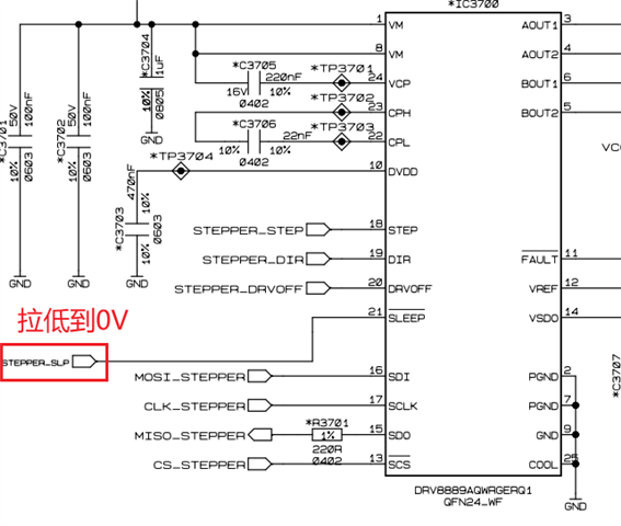
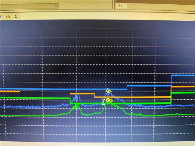
Our customer encountered some EMC problem in the lighting application. They found that the over-limit near the 80M frequency was strongly correlated with the working state of the DRV8889, when force the device to sleep mode, the EMC problem around 80MHz can be settled down.
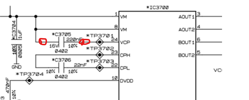
We preliminarily judged that the 80M EMC issue may be caused by the outward conduction of the charge pump, can you help confirm:
1. Which part of the DRV8889 is the 80M EMI likely to be generated from?
2. What is the frequency of the Digital oscillator?
3. What is the switching frequency of the A B phase current chopper control
4. What are the corresponding optimization and improvement measures, such as how to adjust the spread spectrum of the charge pump, reduce the output voltage and current of the charge pump, etc.
Thanks a lot.