


Hi, TI expert
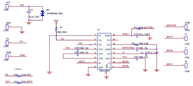
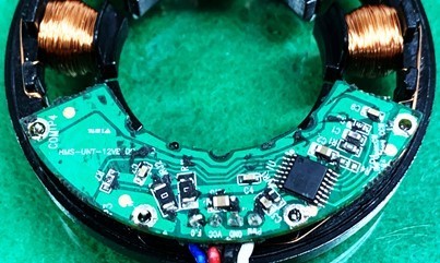
Our customer is using the DRV11873PWPR for the stirring motor used in the water purifier.
However, due to continuous defects, there are inquiries as to whether the surge resistance can be increased to check if there are any problems with the circuit and to supplement the surge protection circuit.
* Failure phenomenon
1. Internal FET burnout on FG output side,
2. PWM input burnout,
3. There are various defects such as FET burnout on the Vcc motor drive side.
- The motor is 12V 4.5W 2500rpm, the phase resistance is 6.15ohm, and the starting current (inrush current) when the motor starts is 0.75A.
- In the case of FG output, the Vcc terminal is connected to a 12V pull-up, and there is no pull-up in the water purifier side circuit.
- The PWM input side applies a soft start function by linearly applying 5V 20kHz Duty 0~100% for 1 second when the motor starts.
- After 1 second, 5V is input, and there is no separate PWM speed control depending on the water purifier conditions.
- In the case of FG and PWM, it is necessary to apply a circuit that separates them with Tr, etc. rather than a photo coupler, and in the case of the power supply, it is necessary to review the protection circuit against surge and the conditions that may cause a phase short.
Q1) Please review to see if there are any problems with the circuit. (Is there anything that can be improved in terms of circuitry regarding the defect phenomenon?)
Q2) The attached files below are defect review reports. Do you have any advice on how to improve the defect?
AGITATOR MOTOR (Failuer_short defective).pptx
AGITATOR MOTOR_PWM short defective.pptx
AGITATOR MOTOR_PWM-FG ERROR Failuer.pptx
Please check. Thank you.
