This thread has been locked.

If you have a related question, please click the "Ask a related question" button in the top right corner. The newly created question will be automatically linked to this question.

DRV8316: The slope of the no-energized period appears to be reversed. How to align and start up the BLDC motor to get the correct waveform?

Part Number: DRV8316
Other Parts Discussed in Thread: MCT8316A

Hi, team.

I've heard it before, but please let me know how to to align and start up the BLDC motor to get the correct waveform?

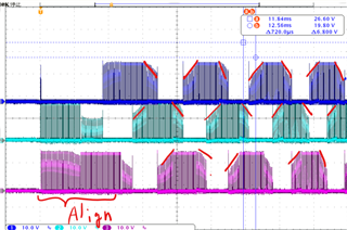
The problem is slope of the no-energized period appears to be reversed as shown in fig.1.
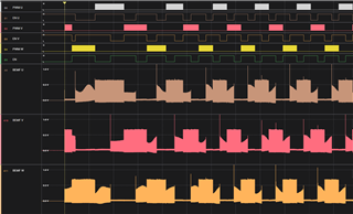
I would like to get the waveform shown in fig.2 at startup.
(The waveform at startup of a commercially ESC will immediately look like fig.2.)

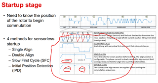
I use double align for start up like fig.3.
Is it necessary to monitor voltage or current values during the align period for a successful startup?

fig1. My BEMF waveform at start up and open loop control 

fig2. Desired Waveform

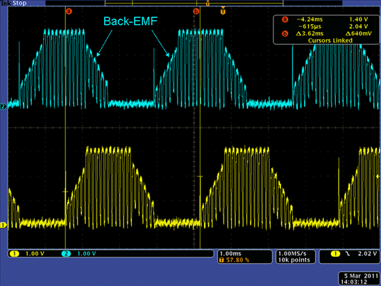
fig.3 Stages of Motor Control TI Precision Labs – Motor Drivers page 6

  • Hey Kenji-san,

    Would you be able to share some insight into how you were able to resolve this issue in the linked E2E? And what is different between these two projects?

    Best,

    Akshay

  • Hi Akashay-sna.

    Previously, I was able to solve the problem by increasing the rotation speed and using software.
    However, it is a temporary solution.

    What I basically want to know is how to start a BLDC motor in trapezoidal control.
    And how to obtain a trapezoidal waveform immediately after startup.

    Figure 1 shows the waveform after startup of a commercially available ESC. After aligning twice, a trapezoidal BEMF is obtained.
    I have used the MCT8316A, and also immediately obtain a trapezoidal BEMF waveform.

    However, if I implement it myself, can't get good waveforms.

    How  align the rotor and stator after startup?

    fig.1 commercially ESC start up waveform

    fig.2 my start up 

  • Hey Kenji-san,

    Sensorless startup is challenging without enough back EMF, so increasing speed helping makes sense. I will need to consult my team on what can help as this seems to be FW related.

    If MCT8316A's FW works the to give the desired output, then is there any challenge in using that part for your project?

    Best,
    Akshay

  • Hi, Akashay-san.

    MCT8316A is trapezoidal control integrated driver by TI.
    So, I can't know how it controlled.

    I would appreciate it if you could give me some helpful advice regarding startup.

  • Hey Kenji-san,

    Sure, I can consult my team for some suggestions and get back.

    I was curious to see if the integrated control of MCT from our team would work for your application.

    Best,
    Akshay

  • Hey Kenji-san,

    For sensorless startups in your systems it seems like the alignment is not happening correctly leading to the offset seen in the waveforms. 

    You can try to align the rotor to a known position on the MCT device and measure the Phase voltages and currents to see how the FETs are commutated to implement a similar FET firing in your system.

    I am not able to share much detail on the FW of our sensorless control itself. 

    Our DRV832xEVM has a sensorless Trapezoidal solution that can offer some background:

    link to User'sGuide: https://www.ti.com/lit/ug/slvub12/slvub12.pdf?ts=1712687468903

    Best,
    Akshay