This thread has been locked.

If you have a related question, please click the "Ask a related question" button in the top right corner. The newly created question will be automatically linked to this question.

MCF8315C-Q1: Register value

Part Number: MCF8315C-Q1

Tool/software:

Dear team,

My customer found the following two questions when using the MCF8315C-Q1 chip. I hope they can be confirmed and explained:


1) The power-on default values of the registers are inconsistent.
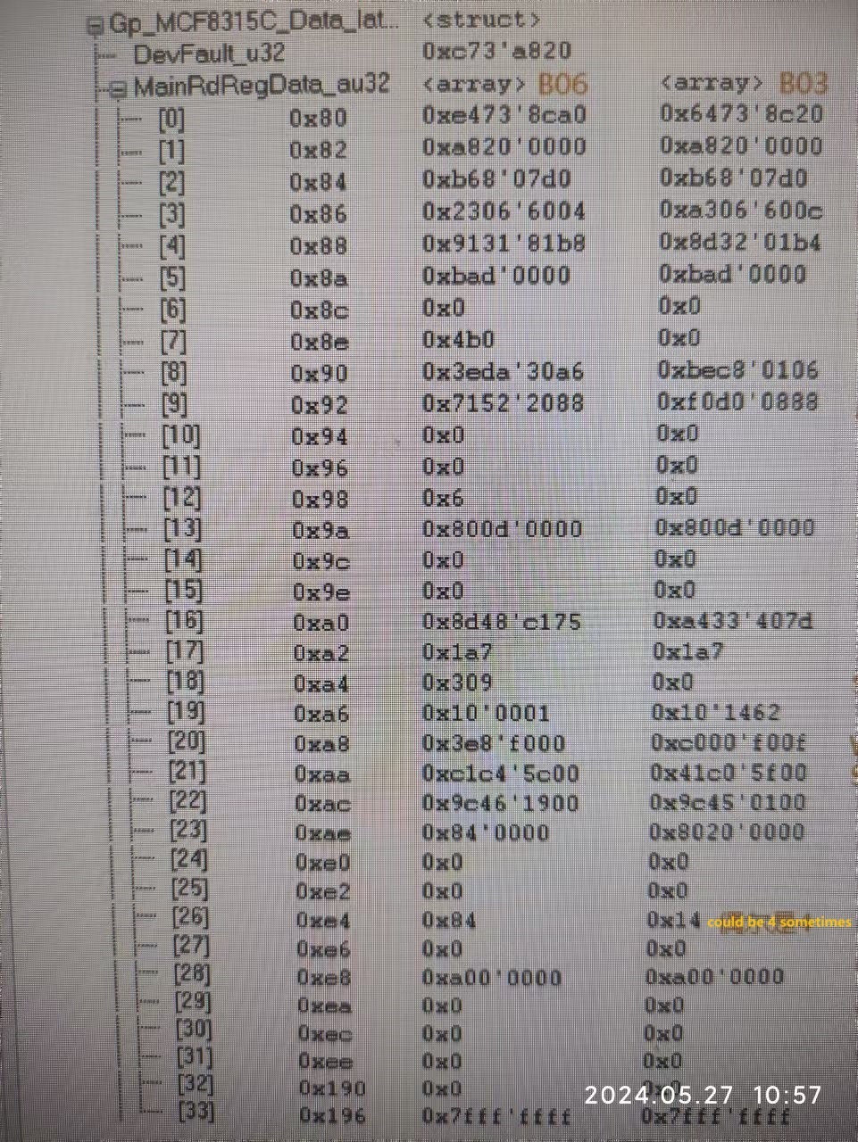
We have two MCF8315C-Q1 chips with different silk screens as shown below. After powering on, we read their register values and found that several register values were inconsistent, as shown below. What is the reason? What do AQLK and ARBP stand for? Are the registers set in advance before leaving the factory?
a:MCF8315ACVQ1 TI 488 AQLK 64
b:MCF8315ACVQ1 TI 438 ARBP 64

2) Based on the register values read above, compared with the latest version of the MCF8315C-Q1 chip manual SLLSFV6-JANUARY 2024, it is found that the RESERVED bit of some registers is not 0. Is it normal? and how to deal with it?

  • Hi Mingkang,

    1. The device markings are lot trace information used to identify fabrication plant, date, etc.
      The MCF8315C-Q1 have non-volatile EEPROM registers that get programmed in factory during the device testing/trimming. The default factory register values can be different between different device lots if there had been changes to the test program. However, I'm not aware if there has been any updates to the factory test program.

      Is the customer certain that the devices are brand new from factory, and that their EEPROM registers haven't been re-programmed? It's possible that the EEPROM  registers in these devices had been written to different values, and that's why they are showing different values on power-up. They can always simply reprogram the EEPROM values to their desired configuration (tuned for their motor).

      FYI, this device’s EEPROM registers have a mirror copy called the shadow registers that reside in RAM. When regular I2C commands are sent, you are directly interfacing with the shadow registers. Here's a block diagram to better visualize the register memories in the device:


      Some of the registers in the list above are also RAM registers that can change based on the device operation. Only the EEPROM registers will remain consistent on power cycle.
    2. The reserved bits don't affect the algorithm, so there's no effects if they are set to 0 or 1. I would simply recommend leaving them as 0 when writing the settings into EEPROM.

    Regards,
    Eric C.