This thread has been locked.

If you have a related question, please click the "Ask a related question" button in the top right corner. The newly created question will be automatically linked to this question.

DRV8462: Motor drivers forum

Part Number: DRV8462

Tool/software:

Hello Ti,

Greetings of the day!

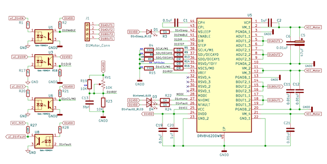
I designed a PCB to run Stepper Motor with DRV8462 Driver. Design Snap attached below.

I'm facing few major issues with it mentioned below:

  • With Manual Hardware Interface :  
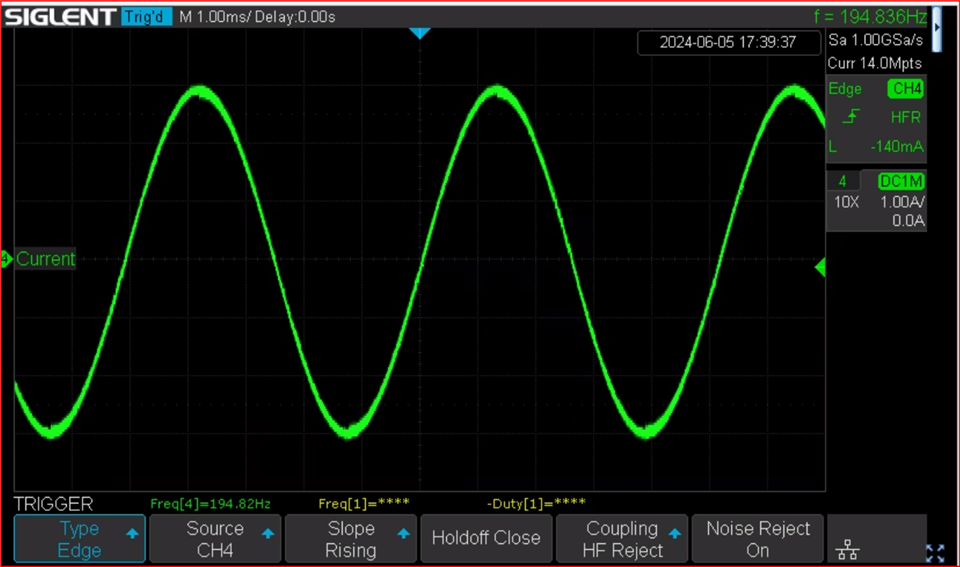
    • Even with 100 kHz PWM on Step Pin, I'm not getting enough speed with this driver, micro stepping was set to 1/128(both mode pins left open). Also when I'm running motor for a while, it is getting heated up, and going into thermal shutdown.
  • With SPI Interface :
    • Steps are missing even on no load, motor is running with jerk, and also not getting enough speed. On startup it is demanding high current, even more than motor rated current, also heating in a while.
    • Is there only way to set the STEP bit in CTRL2 Reg, to run the stepper motor only single step. Is it not possible to run the stepper by giving number of steps, and motor keeps running standalone until the step count ended up?
    • Is there way to control the acceleration and deceleration?

I've tried almost every possibility I could understand from DRV8462's datasheet like, HW interface, In SPI Interface(stepping through SPI), Auto Micro-stepping, Auto torque, Decay Modes, Activating both rising and falling edge for stepping etc but could not achieve enough speed. I need to run the motor around 250 RPM, but currently it is running only around 25 RPM while the motor can run up to 1000 RPM as per its datasheet. Even we have run this motor up to 500 RPM with a driver module TB6600 without any issue.

I'm attaching Schematic snap and Code I'm working on. Please let me know if any further details are required and suggest the way forward.

DRV8462_Own_Code.zip

  • Hi Vishesh,

    If you were able to run the same stepper with the 6600 device using the same supply voltage and Ifs settings you should be able to achieve the same with the DRV8462 in either HW or SPI modes.

    If appears that you were running into thermal shutdown of the device. This points to an issue with the PCB you have and how it dissipates heat from the DRV8462DDW device. Have you tried the same motor with TI DRV8462EVM? I did not notice anything unusual in your schematic that you shared in your post. 

    Could you please share the current waveform of either A or B phase? What was the supply voltage used for the test? What was the IFS current settings? Thank you.

    Regards, Murugavel

  • Hi Murugavel,

    Thanks for your prompt reply.

    • It appears that you were running into thermal shutdown of the device. This points to an issue with the PCB you have and how it dissipates heat from the DRV8462DDW device. >>
      • PCB is 2 Layer with 3oz Copper, the exposed pad is connected to GND Copper Pour on Top side and connected to bottom copper pour through stitching vias. Heat sink is also installed. For better clarity I'm attaching my Thermal calculation, Board layout and and Setup image. Please check and let me know if I'm making any mistake.
    • Have you tried the same motor with TI DRV8462EVM? >> 
      • I'm not having EVM board and neigher I'm able to arrange it.
    • I did not notice anything unusual in your schematic that you shared in your post. >> 
      • Thanks for reviewing it, but I found one mistake in my schematic that I have shorted VCC with DVDD pin due to unavailability of external supply in proto board. But due to this I pulled up the nSleep Pin with DVDD supply only and DVDD generates only after nSleep is pulled HIGH. I would like to seek your attention on this point to update this in datasheet because in Pin description for VCC it written that "Supply voltage for internal logic blocks. When separate logic supply voltage is not available, tie the VCC pin to the DVDD pin."  This somewhat ensures that in any condition external supply is not a must. Although in nSleep pin detailed description, need of external controlled is properly mentioned but here itself it should have been mentioned that nSleep pin should be controlled through GPIO or pulled through external supply.
    • Could you please share the current waveform of either A or B phase? What was the supply voltage used for the test? What was the IFS current settings? >> 
      • I'm unable to capture the current waveform due to unavailability of any shunt resistor or current probe, but I'm attaching few snaps of voltage waveform capture in different condition along with TB6600 waveforms for comparison.
      • HW Interface Setup for DRV8462: 
        • Supply Voltage : 24VDC
        • IFS : 3.78A (I should have been 3A but due to inappropriate resistor value Vref is set to 2.5V instead of 1.98V)
        • Microstepping : 1/128 (both Mode pins left open in Hi-Z state)
        • Decay Mode : Smart Tune Dynamic Decay (Both Decay mode pins pulled to GND through 10K)
        • Step Frequency : 100KHz
      • SPI Interface for DRV8462 :
        • Supply Voltage : 24VDC
        • IFS : 3A (Please correct me If I'm making any mistake in calculation IFS) 
          • VREF_INT_EN Bit Set to HIGH (Ignoring Vref Pin Voltage)
          • IFS (A) = 3.3 V x TRQ_DAC / KV (V/A)
          • for Ifs = 3A, TRQ_DAC has to be 3/5, means 60% of 2^8(TRQ_DAC Register max value) = 153 =  0b10011001
        • Microstepping : Auto Microstepping
        • Decay Mode : Default 111b = Smart tune Ripple Control
        • Step : Controlled trough SPI Step Bit
        • Torque : Auto Torque Enabled
          • Minimum Current is set to 1A(In Code : Set_ATQ_LRN_MIN_CURRENT = 0x30)
          • Final Current is set to 2.5A(Set_ATQ_LRN_STEP = 0x0C)
          • Learning Cycle : 32 Half Cycle for stable learning(Set_ATQ_LRN_CYCLE_SELECT = 0x03
          • ATQ_FRZ[2:0] : 111b - Slowest response, but the loop will be stable
          • ATQ_AVG[2:0] : 111b - 8 cycle average
      • TB6600 Setup:
        • Supply Voltage : 24VDC
        • IFS : 3.5A (To Match with DRV8462 Setup)
        • Microstepping : 1/32 (max available on Driver, to match with the DRV8462 Setup, Step frequency was reduced in same ratio, 1/4th)
        • Decay Mode : Not Available, Internally managed
        • Step Frequency : 25KHz
      • All possible voltage waveforms are attached with explanation in its name.
    • You did not give any information regarding acceleration and deceleration control with DRV8462 and running by giving number of steps instead of controlling it for each step, I asked in my post, please guide on these as well.

    Please let me know if any further details are required to assist me.

    DRV8462_Captures.zip          Stepper_Driver_PCB_V1-for_TI_Support.zip           Thermal_Calculation-drv8462.pdf

  • Hi Vishesh,

    Thanks for the additional information. I have an NEMA17 stepper with me that I hooked up to a DRV8462EVM (this carries the DDW package of the device). I set it up for 3A with internal ref and TRQ_DAC = 60%, 24V supply in SPI mode. Automicrostepping enabled and STEP rate set for 234 RPM. Decay is STRC. The motor runs as expected with no issues. See below the current waveform. This was with auto-torque disabled.


    After running for 30-mins the device temperature was 134C. There is no way to install an heat sink to the DRV8462DDW package. If you stick a heatsink on the top of the IC it will not be that effective but might help a little bit. We do have a DRV8462DDVR in a different package that allows top mounted heatsink. What was the device temperature measured in your application while the motor is running at the target speed. Your thermal calculation yielded 58C @ 3A. Something must've been missed in the calculation resulting in a big difference even with the 6-layer EVM board. Please check out this thermal calculator, "[FAQ] How to estimate die temperature of Stepper Driver?" https://e2e.ti.com/support/motor-drivers-group/motor-drivers/f/motor-drivers-forum/1166656/faq-how-to-estimate-die-temperature-of-stepper-driver?tisearch=e2e-quicksearch&keymatch=FAQ%20stepper%20die%20temperature%20estimat.

    You mentioned autotorque was enabled. Did you perform a learn operation and also tune the values of kP and kD? If not auto-torque will not work correctly. See application note, https://www.ti.com/lit/an/slvaff1/slvaff1.pdf. I'd recommend to conduct tests with auto-torque disabled while in SPI mode. 

    The voltage waveform does not give the full picture. The decay operations between the two chips will be different, comparing voltage waveforms does not mean much. I'd need the current waveform of either A or B for further diagnosis.  

    I had a similar (to SPI mode) performance at 234 RPM in HW mode as well. I also increased the current to 3.5A. There was no thermal shutdown with the EVM setup. Also note the device will run cooler in lower microsteps setting because of lower switching losses in the device. So for 3A, 1/16 steps 234 RPM the temperature of the device was 74C.

    "I have shorted VCC with DVDD pin due to unavailability of external supply in proto board.". This means the MCU GPIO logic HIGH level must be 5V. This is a valid connection for 5V logic. For 3.3V logic HIGH level VCC must be connected to 3.3V. VCC pin function is described in the pin table which is correct. 

    In your schematic for the nSLEEP pin I noticed you had a netlist D1nSLEEP on the pin. I assumed that was coming from an MCU GPIO control. Yes you cannot have nSLEEP tied to DVDD. The device will never wakeup. We've mentioned this in the datasheet.

    I'm unable to open the gerber files you sent me. Can you make a pdf of the layers and resend? I'm not 100% sure you were running into thermal shutdown. That was a suspicion based on your description. As long as the thermal requirements are satisfied it shouldn't be an issue for 2-layer boards to support the driver functionality. Keeping in mind at 24V switching losses can become substantial at higher switching frequencies both with microstepping and internal current regulation PWM tON and tOFF cycles. 

    "You did not give any information regarding acceleration and deceleration control with DRV8462 and running by giving number of steps instead of controlling it for each step, I asked in my post, please guide on these as well.". the DRV8462 supports STEP and DIR inputs. acceleration and deceleration must be provided externally with the STEP input - ramp up and ramp down. Likewise this device does not have inputs for number of steps. This must also be managed in the external MCU. 

    Regards, Murugavel