DRV3946-Q1: Using CMD1 does not let me change the state of the Channel 1 Solenoid

Part Number: DRV3946-Q1

Tool/software:

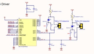
I am using the drv3946 to control solenoids.  When using the CMD1 register, I am unable to get the Channel 1 solenoid to turn off.  Channel 2 seems to work fine, however when using CMD1 with  0x09 or 0x08 as per the instructions in section 7.5 of the DRV3946-Q1 pdf file, the drv3946 keeps the Solenoid powered.

I have tried setting the EN/EN1 DIS/EN2 control bit in the configA register space set to both individual and combined, and have tried all combinations of setting for those bits with no success.

I have disabled all warnings and nFAULT shows as high.

I have also tried disabling nFAULT reporting as well as all warning reporting.

PVDD is at 24volts, VDD is at 5 volts.

I am using the CRC algorithm in the Demo board's MCU source file and do not appear to be getting CRC errors in the command register writes.

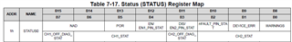
A register dump shows the following

(This is how they are currently set up, I have tried different settings

Spi Read gave us Register Addr 0x10 rdata ->  0xc0 0x40
Spi Read gave us Register Addr 0x11 rdata ->  0xc0 0x40
Spi Read gave us Register Addr 0x12 rdata ->  0x24 0x24
Spi Read gave us Register Addr 0x13 rdata ->  0x0 0x88
Spi Read gave us Register Addr 0x14 rdata ->  0x13 0xc
Spi Read gave us Register Addr 0x15 rdata ->  0x80 0x0
Spi Read gave us Register Addr 0x16 rdata ->  0x0 0x0
Spi Read gave us Register Addr 0x17 rdata ->  0x26 0x23
Spi Read gave us Register Addr 0x18 rdata ->  0x0 0x40
Spi Read gave us Register Addr 0x19 rdata ->  0xb 0xb
Spi Read gave us Register Addr 0x1a rdata ->  0x80 0x0
Spi Read gave us Register Addr 0x1b rdata ->  0x0 0x0

I'm. not really sure what to try next. The hardware looks correct as far as I can tell, as the design was based around the evaluation board's design.

Any suggestions would be appreciated.

Thanks

Rick

  • Hi Rick,

    Thanks for the question. Can you also give the the Status register reads (Address 0x01 to 0x04, 0xA and 0xB).

    Thanks,

    Ibinu

  • Gladly!  Here you go.

    Spi Read gave us Register Addr 0x1 rdata  = 0x5 0x88
    Spi Read gave us Register Addr 0x2 rdata  = 0x8 0x2
    Spi Read gave us Register Addr 0x3 rdata  = 0x0 0x0
    Spi Read gave us Register Addr 0x4 rdata  = 0x0 0x0
    Spi Read gave us Register Addr 0xa rdata  = 0x0 0x0
    Spi Read gave us Register Addr 0xb rdata  = 0x0 0x0

  • Oh, as a side. note,  Ideally what I would LIKE to do is get the device setup so that I can use the EN lines to control the valves, is this possible? My hardware engineer and I are not sure if this can be done.  Then I can just use the SPI to clear faults and check status. 

    Thank you

    Rick

  • Sorry, yet another detail ..  I should mention that the devices are currently open circuit and I am testing for actuation by measuring the voltage at the output of the drv3946.. 

  • Also seeing the arc for configs and config b seems to be incorrect, I'll work on fixing that. (I'm using the arc algorithm in the source code for the dev board MCU)

  • SO I fixed the arc issue with the config registers , here's the output of status0 and status1

    Spi Read gave us Register Addr 0x1 rdata = 0x4 0x88
    Spi Read gave us Register Addr 0x2 rdata = 0x8 0x0

    However, now I have no control over turning the solenoids on or off at all. Slight smile

    I've also tried using the en lines to see if they work or not, so far no go.

  • Hi Richard,

    From the STATUS0 registers, CH1_OFF_DIAG_STAT & CH2_OFF_DIAG_STAT seems to be High. This could be because of the load not being connected(You can get the details of this from the off state diagnostics section in the datasheet for details on this)

    And in case the load is not connected, the device will continue to be in STANDBY state and you will not be able to see the OUTPUT node  switching. 

    My recommendation would be to follow the steps

    1. connect the load 

    2. CLR_FAULT command to clear  the faults  

    3. CMD1 register can be written to program CH1_CTRL and CH2_CTRL to the desired setting.

    4. Make EN/EN1 as High for the contactor to be turned ON.

    Thanks,

    Ibinu

  • Hi RIchard,

    In the SPI read of 0x1 the 0x50x88 seems a little unlikely, this would  mean that the NAD address is 01. since the first 2 bits of status 0 indicates NAD address. From the other registers I gather it to be 0x00. Let me know if this is correct.

    Thanks,

    Ibinu

  • Yes, this is possible. Once you program the initial registers the contactor can be controlled by EN/EN1 pins for the ON and OFF functionality.

    Thanks,

    Ibinu

  • Thank you for the information.

    I have connected the solenoids and followed your set of instructions...  It would appear that I now have some other issue with over or under current?

    I will need to adjust what the settings are for the device to activate the solenoids as they are still not being turned on...

    This is the register dump for the device.

    Spi Read gave us Register Addr 0x1 rdata  = 0x3c 0x0
    Spi Read gave us Register Addr 0x2 rdata  = 0x38 0x0
    Spi Read gave us Register Addr 0x3 rdata  = 0x0 0x0
    Spi Read gave us Register Addr 0x4 rdata  = 0x0 0x0
    Spi Read gave us Register Addr 0x5 rdata  = 0x0 0x0
    Spi Read gave us Register Addr 0x6 rdata  = 0x0 0x0
    Spi Read gave us Register Addr 0x7 rdata  = 0x0 0x0
    Spi Read gave us Register Addr 0x8 rdata  = 0x0 0x0
    Spi Read gave us Register Addr 0x9 rdata  = 0x0 0x0
    Spi Read gave us Register Addr 0xa rdata  = 0x0 0x0
    Spi Read gave us Register Addr 0xb rdata  = 0x0 0x0
    Spi Read gave us Register Addr 0xc rdata  = 0xba 0x4d
    Spi Read gave us Register Addr 0xd rdata  = 0xbb 0x4d
    Spi Read gave us Register Addr 0xe rdata  = 0x0 0x0
    Spi Read gave us Register Addr 0xf rdata   = 0x0 0x0
    Spi Read gave us Register Addr 0x10 rdata  = 0xc0 0x40
    Spi Read gave us Register Addr 0x11 rdata  = 0xc0 0x40
    Spi Read gave us Register Addr 0x12 rdata  = 0x24 0x24
    Spi Read gave us Register Addr 0x13 rdata  = 0x0 0x88
    Spi Read gave us Register Addr 0x14 rdata  = 0x13 0xc
    Spi Read gave us Register Addr 0x15 rdata  = 0x80 0x0
    Spi Read gave us Register Addr 0x16 rdata  = 0x0 0x5
    Spi Read gave us Register Addr 0x17 rdata  = 0x26 0x23
    Spi Read gave us Register Addr 0x18 rdata  = 0xff 0xff
    Spi Read gave us Register Addr 0x19 rdata  = 0xb 0xb
    Spi Read gave us Register Addr 0x1a rdata  = 0x80 0x0

    I will get the solenoid details from my hardware engineer. He had mentioned that we will need to do some tuning of certain resistors in the circuit that the drv3946 uses to determine what the current range to use is? The riprap currents I believe he stated?

    Thank you for your help so far!

    Rick

  • Unfortunately, this did not work. I have teh loads attatched, and sent out the commands but the relays still do n ot want to actuate.  I'm at a severe loss as to what's going on here. 

    There is one thing I found that is different between the demo board and our impementation. The hardware designer added an EMI suppression diode as shown in the schematic snippet I will include here.. diodes d2 and d5

    Would that possibly be preventing this from functioning?

  • Hi Richard,

    Thanks for your patience. From the register settings (Status 0, Address1h, Bit 13)  it looks like the POR Bit is High. 

    This would mean that the power up is complete and the device is ready to goto Standby State. However for the device to goto standby state we will have to provide a CLR_FAULT command. The device can go into Active state once it reaches the Standby state.

    The diodes should not be causing startup issues , however we will have to understand how the current regulation happens once you are able to start up.

    In the schematics I don't see the Ripropi resistor value, The programming of Config A0 and Config A1 (Address 10h and 11h) will depend on the current requirements of the contactor and Ripropi. I have attached a calculator to find the register bits for the same. Let me know if it helps.

    Thanks,

    IbinuPC_HC_calculator.xlsx