DRV3946-Q1: PVDD_OV gets asserted on adjacent valves when a valve is shut off.

Part Number: DRV3946-Q1

Tool/software:

Greetings,

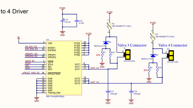
I've run into an interesting issue with the DRV3946 driver.

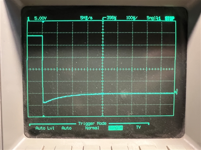
We have an application that uses 4 of the drv3946's to drive 8 valves.  The valves are close to each other (about 3mm) and when the wire to control the valve is run between the valves, disabling a valve will induce a PVDD_OV response on the valves adjacent to the valve that has been deactivated.   We have rerouted the wires so that they are not running between valves and this has helped, a bit, but the error still occasionally occurs. I have tried to increase the PVDD_OV deglitch time to it's maximum value with no effect.

We have also installed a shortly. diode on the output to ground to try and control this spike, so far with no success.

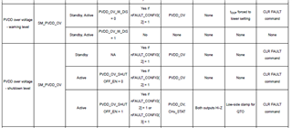
Also, PVDD_OV warning always asserts due to our power supply supplying 24 volts for the valves and the threshold for lvdd_ov warning appears to be 20 volts.

Is there something I can do to mitigate this?  I know I can disable the warning and the error with the control registers, but that seems like it would not be the best idea.

Any insight you can offer would be of help.

Thanks

Rick

  • Hi,

    Thank you for your question. Our expert will feedback to you in a day or two.

  • Hi Rick,

    Thanks for the question.

    Is it possible to get the voltage waveform of PVDD when output is disabled. I wanted to see if the PVDD is increasing due to clamps. A schematic of the circuit also will be very helpful.

    Regarding the OV_Warning, the threshold is 19.7V (typical) and hence it will show the warning for 24V supply. The option here is to disable the warning.(This will not disable the OV which is set around 33V)

    Thanks,

    Ibinu 

  • Here is the trace of the mvdd across the valve when it is turned off.

    And this is the schematic for the outputs of the valve driver. mvdd is at 24volts and vdd is at 5 volts

    The device is configured to use EN1 and EN2 to shut the solenoids off and to turn them on.

    Please let me know your thoughts!

    Thanks you

    Rick

  • Also, a questions a bout OV warning and OV error.. the two are distinct results reported by the DRV3946?  So I will always get the warning (unless I disable it) but if I disable the warning, it will not suppress the error which is triggered at 33voltss? Do I understand this correctly?

    Thanks

    Rick

  • Hi Rick,

    This is very interesting. Can you confirm the need for the diodes in the schematics. We do have a clamping mechanism in the device (QTO) for fast discharge of the currents in the coil while turn OFF. QTO will clamp the output voltage to a higher level than PVDD while output turn OFF. I am wondering if there is some interaction from the diode while the current clamp is happening.

    Can you do a test without the diodes if thats possible.

    Thanks,

    Ibinu

  • Hi Rick,

    As you mentioned warning level and fault level are two seperate thresholds and is done sepeatly inside the device.

    Since you use 24V you will always get warning as you mentioned if it is not disabled

    The details on this can be found in the fault table in the datasheet

    Thanks,

    Ibinu 

  • We did try that , however, we still get that error.. Also I get a lot of threshold errors and I"m not sure how to set up this device to eliminate those.  Here is the result of the removed diode test (It's the last line that reads 0 svs 1 0 that turns off valve one) and as you can see the valve next to it gets the error. This is due to the magnetic field of the valve 1 collapsing and inducing a current in valve 2 which gets read as an error.

    ERRor: CODE=314 ATTR=CONTROLLER_2 Maximum threshold violation set by QTOT_MAX_THRS
    ERRor: CODE=200 ATTR=VALVE_6 Short to ground or open, loss of valve control
    ERRor: CODE=200 ATTR=VALVE_5 Short to ground or open, loss of valve control
    ERRor: CODE=404 ATTR=CONTROLLER_3 PVDD is over allowable voltage
    ERRor: CODE=314 ATTR=CONTROLLER_3 Maximum threshold violation set by QTOT_MAX_THRS
    ERRor: CODE=200 ATTR=VALVE_8 Short to ground or open, loss of valve control
    ERRor: CODE=200 ATTR=VALVE_7 Short to ground or open, loss of valve control
    ERRor: CODE=404 ATTR=CONTROLLER_4 PVDD is over allowable voltage
    ERRor: CODE=314 ATTR=CONTROLLER_4 Maximum threshold violation set by QTOT_MAX_THRS

    0 svs 1 1
    0K: SEQ_ID=0 Valve state changed to 1
    ERRor: CODE=311 ATTR=CONTROLLER_1 Maximum threshold violation set by CHx_PT
    ERRor: CODE=318 ATTR=CONTROLLER_1 Minimum threshold violation set by HRT_MIN_THRS
    ERRor: CODE=208 ATTR=CONTROLLER_1 Under current lock out warning
    ERRor: CODE=222 ATTR=CONTROLLER_1 Ripple low warning during hold current regulation
    ERRor: CODE=224 ATTR=CONTROLLER_1 Hold current low current warning during hold current regulation
    0 svs 1 0
    0K: SEQ_ID=0 Valve state changed to 0
    ERRor: CODE=200 ATTR=VALVE_2 Short to ground or open, loss of valve control

    Thanks

    Rick

  • Hi Richard,

    Looks like when you remove the diode, some of the channels get into open load which is being seen as the Short to ground or open, loss of valve control.

    Regarding the other errors : Maximum threshold violation set by QTOT_MAX_THRS seems to suggest that the QTO is really not getting activated.

    I ma curious on what kind of contactor is being used to test here, is it possible to give a datasheet or part number. 

    Thanks,

    Ibinu

  • This is all I have for the device. It's a valve and the version we are using is the 24volt version.