This thread has been locked.

If you have a related question, please click the "Ask a related question" button in the top right corner. The newly created question will be automatically linked to this question.

DRV8307: DRV8307 to change direction, the Motor speed is different ?

Part Number: DRV8307
Other Parts Discussed in Thread: MSP430G2553

Hello ! everyone, I have some problem of DRV8307 

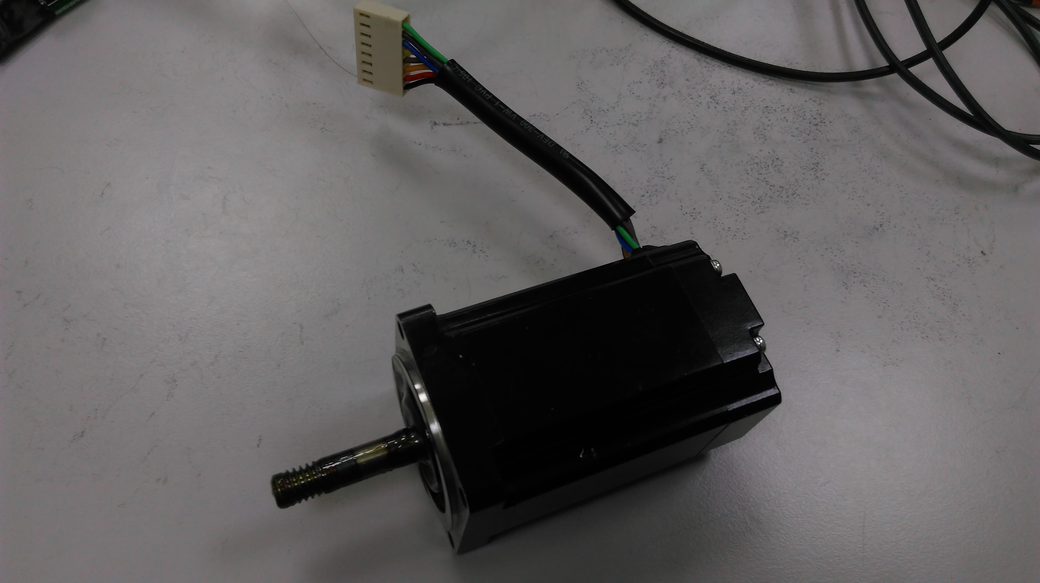
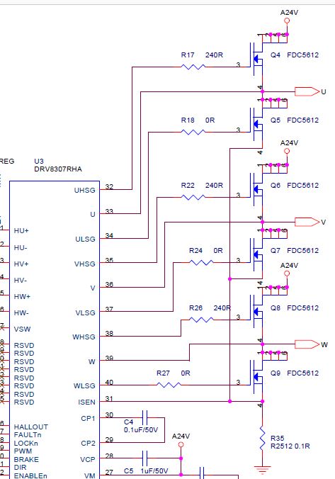
According the DRV8307 EVM Schematic, I design the circuit to drive the BLDC Motor, like the picture below:

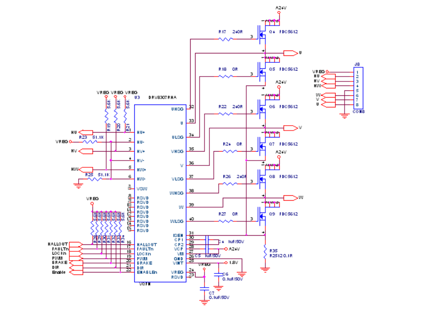
I use msp430g2553 I/O pin to connect to ENABLE,DIR,BRAKE pin,

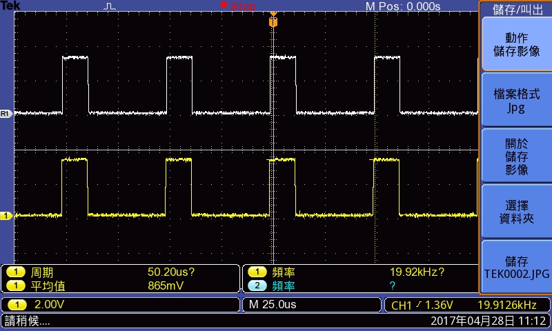
and generate a 20KHz, duty 25% PWM to DRV8307 PWM pin.

start the motor, ENABLE = LOW, BRAKE = LOW,

stop the motor, ENABLE = HIGH, BRAKE = HIGH,

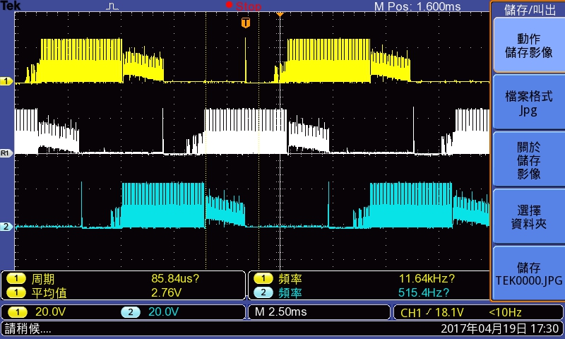
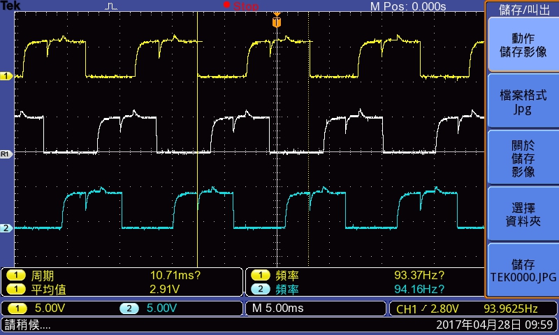
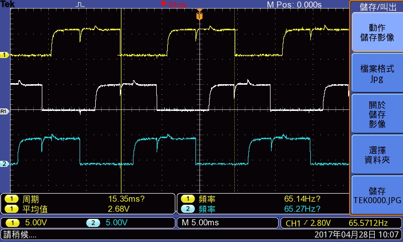
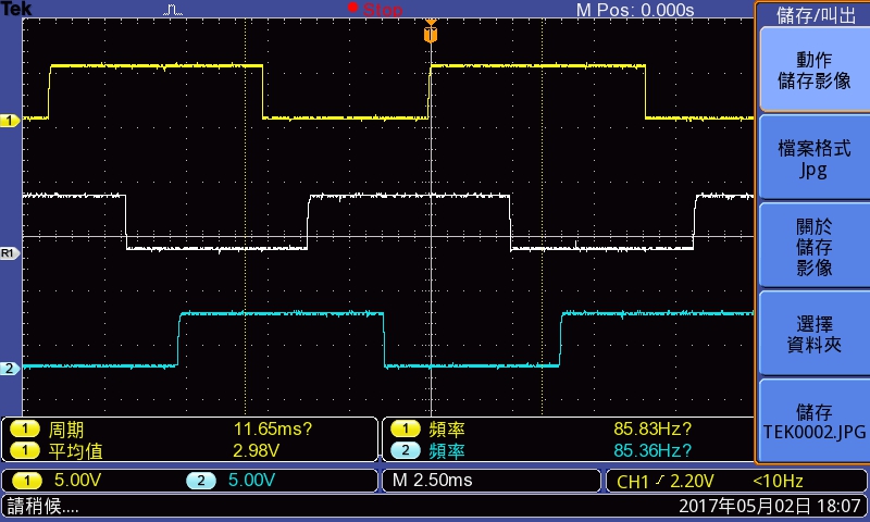
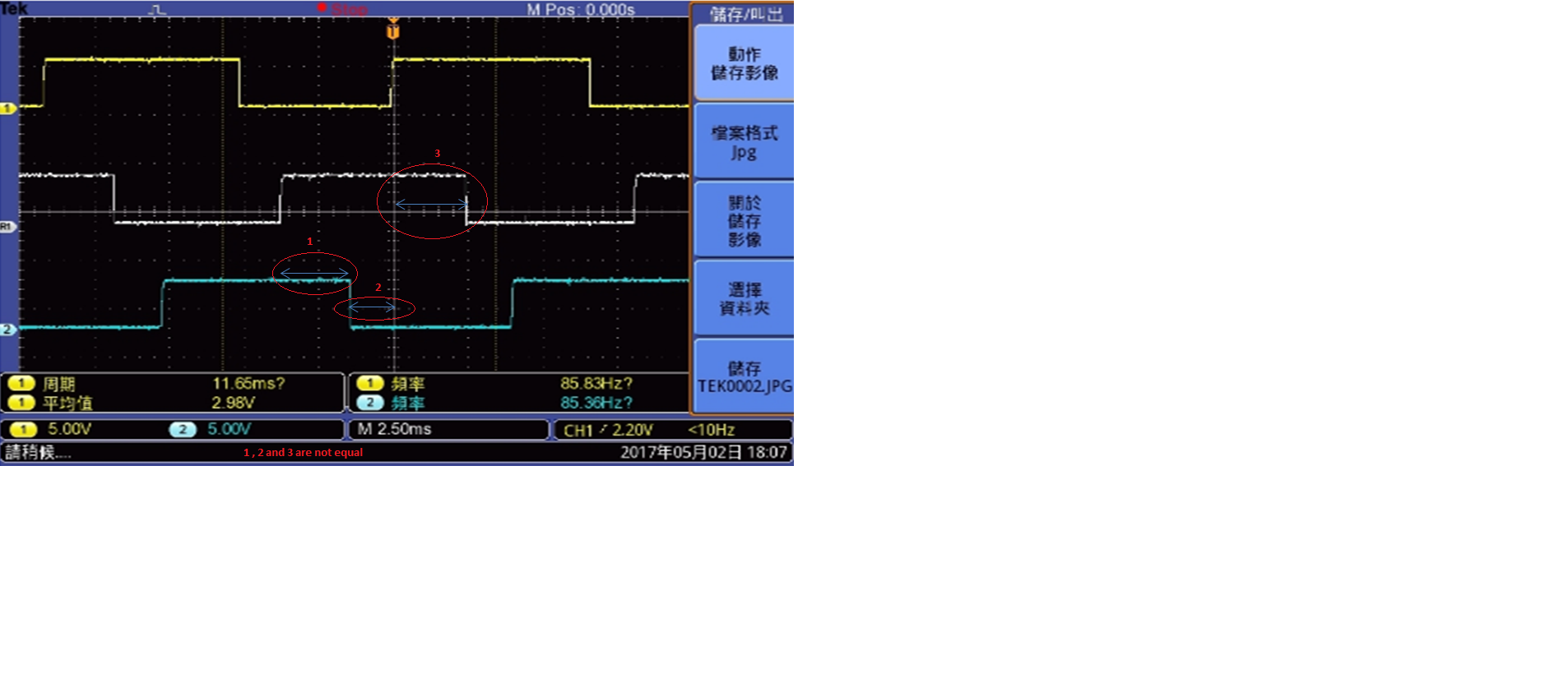
DIR =  HIGH, The motor  rotates Clockwise OK, the motor speed is OK

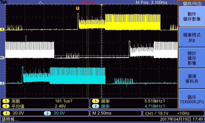
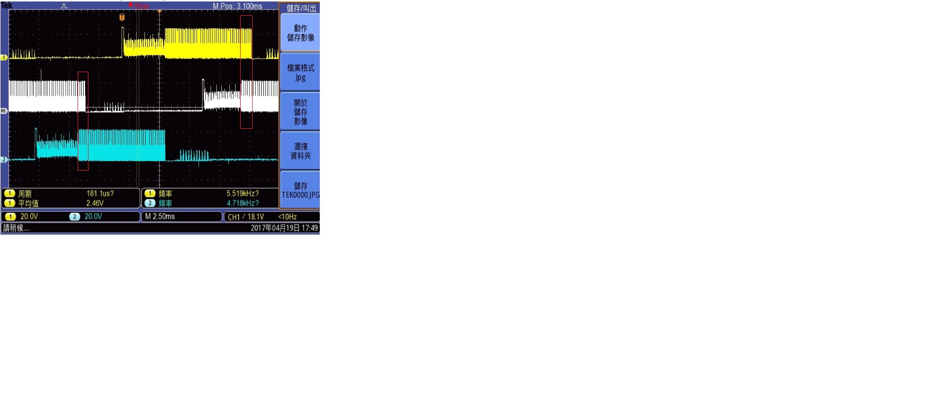
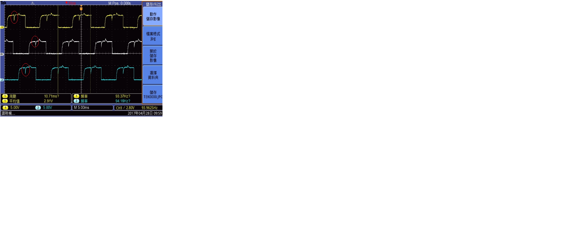
DIR =  LOW, The motor  rotates counterclockwise OK,but the motor speed is slow.

I read the datasheet, everytime start the Motor, Increase the PWM duty 1% to 25% slowly

But the problem is still the same.,Does anyone help me to figure out it ?  Thanks

  • Hi Jossun,

    Can you provide more details?

    What do you mean by the motor speed is slow? What is the speed in clockwise and what is the speed in counterclockwise?
    What type of motor is this?
    Does the load change when the direction changes?
  • Hello, Rick:

    My motor speed is slow, It means U V W Output Frenqency is different with
    the DIR pins set Low & High.

    1.First condition: (Set Motor direction)
    (ENABLE = HIGH, BRAKE = HIGH,) => (DIR = HIGH,)
    => (ENABLE = LOW, BRAKE = LOW,)

    CH1 = U, Reference = V,CH2 = W。The phase is in the picture below:

    2.Second condition:(Set Motor another direction)
    (ENABLE = HIGH, BRAKE = HIGH,) => (DIR = LOW,)
    => (ENABLE = LOW, BRAKE = LOW,)

    CH1 = U, Reference = V,CH2 = W。The phase is in the picture below:

    It seems these U V W phase timing are different when set the DIR pin.

    The phase timing of DIR is low is more longer than phase timing of DIR is high.

    It cause Motor is slower when DIR is low.

    The motor type is WISDOM BLDC 25

    Please help me to figure out what the problem is ?  Thanks!

    Jossun

  • Hi Jossun,

    Can you provide a link to the motor?
    Does the load change when the direction changes?
  • Hello, Rick:

              I don`t have the link of my motor,Because the motor is customized by a company which my boss contact long time ago.

    It not easy to ask the spec. for this BLDC motor. I only know some informations of the motor:

    Output: 25W,voltage:24V DC,Current: 2A,RPM:1000,CLASS:E

    The load of motor doesn`t change when the direction changes.

    The motor active video link:

    Does anyone help me to figure out it ?  Thanks

    Jossun

  • Hi Jossun,

    Phase voltage wave form does not look appropriate. Can you capture the hall signals and PWM signals?

  • Hello, Rick:

    Here are the pictures of the hall UVW signals and PWM signals.

    Hail UVW DIR is high :

    CH1 = Hail U, Reference = Hail V,CH2 = Hail W。The phase is in the picture below:

    Hail UVW DIR is Low :

    CH1 = Hail U, Reference = Hail V,CH2 = Hail W。The phase is in the picture below:

    The PWM phase of MSP430G2553 to DRV8307:

    Frequency: 20K Hz , Duty: 25%

    Thanks!

    Jossun

  • Hi,

    From your phase waveform, it looks like, your controller is applying PWM on two high side switches at the same time or there is an overlap. That’s why there is an overlap in the two phase voltages. Ideally each should be 120 degree apart.

    Each PWM should conduct for 120 degree and there should not be any overlap as shown in the figure.

    From captured PWM waveform it is not clear because its zoomed version. 

    Capture two high side pwm, one low side pwm and one hall signal in same frame (Don't zoom the signal).

  • In captured hall signal there are glitches.These glitches are are not expected. This may lead to wrong commutation.

  • Hi Jossun,

    As Prashant suggested, the glitches could be affecting the operation.

    What pullup resistor do you have on the halls? Can you decrease the resistance to remove the glitches?
  • Hello,Rick & Prashant :

    Thanks your suggestion, I fix the glitches on the phase of Hail Sensor.

    I use the single ended mode on DRV8307, The HU- & HV- & HW- pin are connected to a resistance for 2V of VREG

    I add a 4.7uF capacitance on the resistance for 2V of VREG. The glitches are fixed.

    And I decrease the pull high resistance value from 4.7KΩ to 470Ω. The phase seems to pull high more quickly. 

    like the picture below:


    But the motor still spin left slowly Does anyone help me to figure out what the circuit problem is?

    Thanks for help!

    Jossun

  • Hi Jossun,

    It looks like there is hall misalignment in your motor. Because Ideally each hall signal will be high for 180 degree and low for 180 degree and three are three hall signals. So if you combine all three then you will find every 60 degree one hall edge changes. So in one rotation there will be 6 equidistant hall edges as shown.

    But in captured hall signal its not aligned (verify using oscilloscope).