This thread has been locked.

If you have a related question, please click the "Ask a related question" button in the top right corner. The newly created question will be automatically linked to this question.

Motor tuning problem (took from unsolved support ticket CS0099703)

Other Parts Discussed in Thread: DRV8305, MOTORWARE, TMS320F28027F

Hello,

we try to run a small sensor-less BLDC motor (datasheet attached). We started as recommended with the toolchain: - Motorware.exe -> InstaSPIN-FOC -> Piccolo F2802xF -> GUI -> Universal GUI QSG (PDF) - Code Composer Studio with proj_lab02lc and edit the user.h file - InstaSPIN_UNIVERSAL.exe, using the appProgram.out file generated from proj_lab02c - hardware DRV8305 and Launchpad XL TMS320F28027F, 24V/16A power supply, motor EC1456

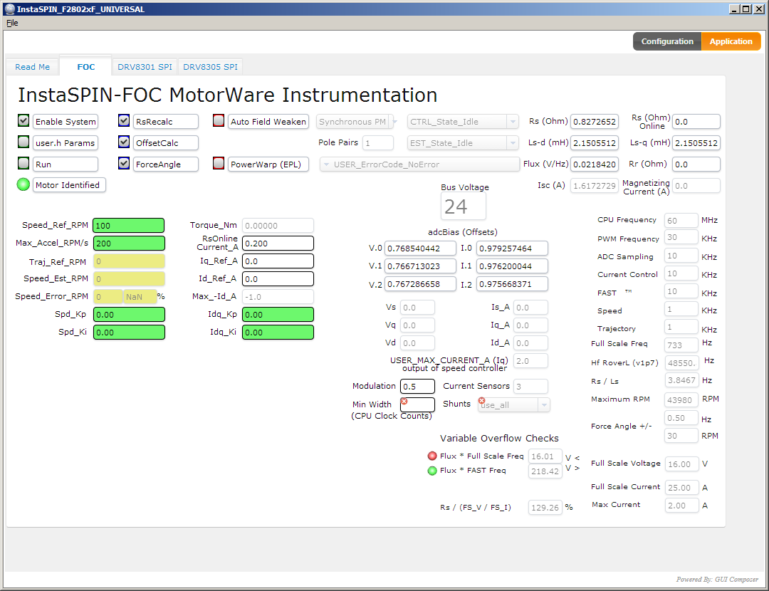
The toolchain works. But running the motor identification in InstaSPIN_UNIVERSAL.exe, we always get different results of Ls-d (mH). The results is any value between 0.0005 and 3.5 mH. The motor identification runs ok with all EST_States, also it speeds up to measure Flux and Ls-d. Sometimes it speeds up to 4000 RPM, sometimes it spins up to 4000, then 27,000. See screenshot attached. But after motor identification, the motor runs sometimes or not. Sometimes we get heavy shaking of the motor at RPMs from 10,000 to 30,000.

What we did to pre-initiialize the parameters in user.h: We use the recommended spreadsheet "docs\labs\ motorware_selecting_user_variables.xlsx" (screenshot attached). We have filled out the yellow fileds und 1. and 2. and the true-checks under 3. are green. Btw, how to continue with 4. and 4. and 5.?

We didn' t find a way to systematically move on with tuning the motor. Please give us advice how to proceed.

Best regards

Alois

motorware_selecting_user_variables.xlsx

1401.user.h

  • Follow the instaSPIN lab guide to run lab02c using CCS directly since you don't know the motor parameters and need to change the identification parameters as well.

    Tuning the below parmeters to spin the motor smoothly based on its specifcation.

    #define USER_MOTOR_RES_EST_CURRENT
    #define USER_MOTOR_IND_EST_CURRENT
    #define USER_MOTOR_MAX_CURRENT
    #define USER_MOTOR_FLUX_EST_FREQ_Hz

  • Hello Yanming, thank you for the reply!

    I will try in run the CCS/InstaSPIN combination. I wonder if there exists an analytic way that provides unique and rock-solid results of the motor development. I'm not the first person trying to run a BLDC motor, so I would expect a solid way here. I've tried

    1. the Quickstart Guide in the MotorWare REsource Exporere PDF,

    2. the Spreadsheet, 

    3. the comments in user.h.

    Following 1. page 28, USER_MOTOR_RES_EST_CURRENT is to be ~10% of rated current = 10% * 1,1 A = 0,11. USER_MOTOR_IND_EST_CURRENT has to be the negative of the rated current, that is -0.11. USER_MOTOR_MAX_CURRENT has to be "Rated peak current of motor required to produce maximum torque. This is HIGHER than the rated current of the motor.". I have tried 1.5 to 3 A, and noted that this is very sensitive. 2.0 A will turn the motor, even 2.1 or 1.9 A will result in heavy vibrations an rotor blocking. I have not idea what happens here. USER_MOTOR_FLUX_EST_FREQ_Hz has to be "~10% of rated max speed", that is 10% of 40,000 RPM * 2 poles / 120 = 67. I would expect that I have done everything correct, right?

    When you say "Tuning the below parameters ... ", do you mean, the above calculation advice in the documentations is only a rough estimation, and one should experiment with the exact values? If, yes, it is not really promising way to develop a product.

    What I know is, that there are motor drivers that work good with exact this EC1456 motor. Unfortunately, the source code is closed...

    Best regards, Alois

  • I followed the chapter lab02.a and lab02.c in the document "InstaSPIN Projects and Labs User’s Guide".

    It turns out that this way is triggering exactly the same functions in the proj_lab02c code, that is, the varables enableSys Run_Identify switched to "1" in the Expressions window run the motor-ID, same way as in the GUI application. The results for Rs, Lsd/Lsq, Flux_VpHz are identical.

    The advice in chapter lab02a is to use the spreadsheet "C:\ti\motorware\motorware_1_01_00_18\docs\labs\motorware_selecting_user_variables.xlsx", what I already did at my first try.

    The advice in this chapters do not solve the problem. I have no idea what's going wrong. So, there is one question:

    The datasheet of the motor states a resistance from phase to phase of 1.30 Ohm. proj_lab02c gets a result of ca. 0.8 Ohm. Furthermore, the datasheet states an inductivity of 76 uH (micro Henry), whereas the lab02c results differ from 500 nH to 5.5 mH !!! Before trying to experiment with parameters and spend hours and days, this should be analyzed before. Why is the measurement so completely wrong?

    / Alois

  • Please follow lab02c and use a higher PWM frequency like 45kHz, and set USER_NUM_PWM_TICKS_PER_ISR_TICK to (3) in user.h.

    Tune the below variables to get a correct Rs first and spin the motor smoothly. Please post the user.h you are using and the datasheet of the motor if you still have any problems.

    #define USER_MOTOR_RES_EST_CURRENT (1.0)
    #define USER_MOTOR_IND_EST_CURRENT (-1.0)
    #define USER_MOTOR_MAX_CURRENT (5.0)
    #define USER_MOTOR_FLUX_EST_FREQ_Hz (20.0)

    Btw, it seems like the motor is too small to the kit, maybe the kit is difficult to achieve current sampling resolution enough for identification.

  • Hello Yanming,

    Thank you for your advice. It is much better now. I copied the parameters into the user.h as noted and the motor turns without shaking. Attached you will find the user.h file and the motors' datasheet. There seems also a difference between the GUI program and the CCS + debugger.

    The result of Rs is 0.823 and Ls is 0.000172.

    The maximum RPM reaches ca. 34,000 whereas the datasheet sates 40,000. Is the algorithm reaching a frequency limit?

    Best regards,

    Alois

    2318.user.h

  • Hello Yanming,

    I'm sorry, I changed the user.h wrong. The above post is _not correct_.

    Using the parameters as you advice, there are problems.

    When setting the parameter USER_MOTOR_MAX_CURRENT to more than 1.1, the motor RPM is somehow modulated at 0 ... 30,000 RPM. It shakes very hard. Above 30,000 the motor runs smooth. The max current of 1.1 A is the nominal curren taken from the data sheet. The torque is ok, but it should be better. Is it possible, that there is a servo loop oscillation?

    Also the maximum RPM of 40,000 is not reachable. When setting SpeedRef_kpm to 40, the actual RPM is around 34,000.

    Alois

  • As mentioned above, Just tell you to tune these variables according to the motor spec. not advise you use these parameters directly. You must use lab02c to identify the correct motor parameters for the subsequent labs first. Recommend you use the CCS to run the lab02c, and then use GUI to run other labs if you want.

    The maximum frequency can be supported by the algorithm, but it is limited to the motor spec. and CPU frequency. Btw, you need to check if the dc bus voltage is high enough for such high speed if the USER_MOTOR_MAX_CURRENT value is large enough.

  • Hi Yanming ,

    The motor runs without shaking and up to a speed of ca. 34,000 RPM (not the rated 40,000 +/-10%). We measured the torque - it is good. Speed changes are possible up to 100,000 RPM/s. So far so good. But there are some issues that I don't understand and I'm not sure about later stable operation under all conditions.

    The values for Rs and Ls result in not so dramatic variation as they were at the beginning, but sometimes a run of Motor-ID in labc results in not working Rs/Ls results - but most of the time they seem correct and the motor runs after then.

    As described in the Quickstart Guide in the MotorWare Resource Exporere PDF, the term, "the USER_MOTOR_MAX_CURRENT shall be higher than the rated motor current" seems to be wrong - at least for our motor type. I don't understand, why this is is the case. The RPM modulation / shaking, that happens once I set the USER_MOTOR_MAX_CURRENT to higher than the rated motor current, seems to be a kind of artefact of PI controller. But to be sure, I had to know how the PI controller works in the motor environment and especially the InstaSPIN interna.

    The rated max. RPM of 40,000, we don't reach at the moment. The power supply has constant 24V. The other dependencies algorothm and CPU frequency, I don't actually understand. I might dive deeper into the source code, but checking source code without software specification documentation is hard. I also might play around with parameters. And why do this when a Quickstart Guide is present and helping starting up easy and faster?

    I think I end with this situation: Take the labc results and leave it, in the hope that it works under all conditions. Not a good feeling, but it works at least for now.

    Thank you very much for all of your advices and your abundance of patience!

    /Alois

  • You are right, the USER_MOTOR_MAX_CURRENT is used for limiting the maximum output torque current of the speed PI regulator. So the USER_MOTOR_MAX_CURRENT should be greater than the rated current of the motor for providing enough torque.

    The result of Rs and Ls may be different every time if the resolution or quality of the sensing current or voltage signals of the motor is not good enough. The motor should spin well if the identification error is not too high.

    As replied above, the maximum speed will be limited to the input voltage or the spec. of the motor, you may need to increase the dc bus voltage or implement field weakening control.