Other Parts Discussed in Thread: TPS63031, TPS22918
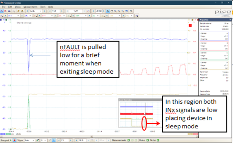
I cannot get FAULTn to de-assert itself after a stall. I have to remove Vcc, as per the OCP (Over Current protection) section.
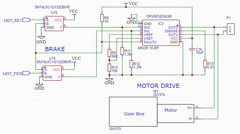
My design with the DRV8832 is 74LVC logic driven rather than a micro, there is no additional PWM happening.
The motor is a small 3V, 100mA worm geared 3RPM with an actuator arm making it simple to apply a stall by hand on the bench.
Vcc tested from 3 to 5V, plenty of on-board capacitance, especially following your layout guidelines.
The Isense resistor is 0.91 ohms and the pull-up on FAULTn is 1K ohm (per your eval board) but also tried 1M ohm.
The OCP seems very unlikely to be a condition (short to ground/supply or motor winding) with such a small motor?
The logic gates apply a brake condition IN1=IN2=HIGH when FAULTn is asserted, a previous iteration of the design did a motor direction reversal, but both have this FAULTn problem.
-
is there a logic/race condition for IN1 and IN2 that might cause OCP to trigger?