This thread has been locked.

If you have a related question, please click the "Ask a related question" button in the top right corner. The newly created question will be automatically linked to this question.

DRV8873HEVM: problem about Fault pin

Part Number: DRV8873HEVM
Other Parts Discussed in Thread: DRV8873SEVM, DRV8873X-Q1EVM

1.When I was using DRV8873HEVM, I found that the motor was working, but the Fault pin light was on. What could be the cause of this, and what test should I do?

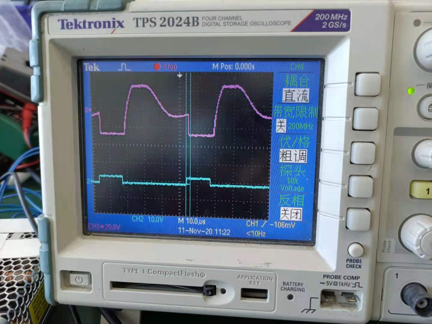
2. What is the frequency of EN/IN1 and can it be set? And what does Ramp Rate mean(in EVM software)?

3. I want to confirm whether Itrip cannot be set in DRV8873HEVM, but can be set in DRV8873SEVM, Is there any other way to set current limit on DRV8873HEVM?

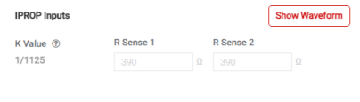
4. As shown in the figure, can Rsense be set via software? I see Rsense=390 in the schematic. What is the effect of setting Rsense in the software?

  • Hello!  

    1)  Please see table 13 in the datasheet for fault response that would result in the nFAULT pin reporting LOW condition.  Is the light on in the GUI or on the EVM itself (physical nFAULT LED is lit)?  How much current are you seeing in the motor when this occurs?  If you can capture the current waveform with a current probe, that would be helpful.

    2)  Frequency is fixed in the firmware and can only be adjusted by modifying firmware.  Should be fixed at 20kHz. Ramp rate is the number of PWM cycles to move from current duty cycle setting to the a new one selected with slider.  This gives some delay instead of immediately moving to increased of decreased duty cycle setting.  

    3)  On the DRV8873H, the current limit is fixed at 6.5A.  See section 7.3.3. in the datasheet.  For the DRV8873S, there are 4 levels selectable with SPI registers.

    4)  You need to set the Rsense in the GUI equal to the resistor on the EVM board.  The default should be what comes installed on the EVM.  If you change this resistor, then change the values in the GUI to match so the current is properly displayed in the GUI.

  • Hi Ryan,

    Thanks for your help ! I will try what you said.

    One more question, Do we have a software development program for DRV8873HEVM? My customer likes to change the chopping frequency when changing directions, he wants to modify it directly in the software program

    BR

    Jenson

  • Jenson,

    Yes, it is online in the EVM tool folder.  Scroll down to the bottom of the page and find "DRV8873x-Q1EVM Firmware".

  • Thanks you for your help! when I disable the OLD ,the EVM not show errors. Is this a problem with the EVM software?

    At the same time, I am very interested. In PWM mode, I set IN2 duty=0 and increase IN1duty. This is the case when the waveform before the motor is not started. Why does this happen?

    BR

    jenson

  • Jenson,

    For the OL issue, lets try one more thing.  Leave it as "activated" like you did before, but after motor is working, try taking nSLEEP pin LOW and then back to HIGH.  This should reset the OL flag and I want to see if error goes away on nFAULT.

    For the PWM operation, this is expected behavior.  Please see table 5 on page 15 of the datasheet.  You are fixing IN2 = 0 and PWM'ing IN1.  When IN1=IN2=0 volts, the outputs go to HIZ state.  

    What you should do instead is fix one of the inputs to HIGH state, "1", and PWM the other input.  Then you will go between a "drive" state and a "brake" state.  The brake state is when both inputs equal "1".  If you want to change direction, force opposite PWM input to "1", and PWM other input.  Please study table closely and figure 10 in the datasheet describing states.  It should then make sense.

  • Ryan,

    Thanks for your help!

    I will ask my customer to try what you said, and I would like to double check in my PWM mode ,the picture show is on Hi-Z status, it is a normal status,right?

    thanks for your help again!

    BR

    jenson

  • Jenson,

    Ryan took vacation this week.

    PWM Mode truth table is proved in the datasheet. They can check the IN1/IN2 signal to confirm the Hi-Z status.