


Other Parts Discussed in Thread: MSP430FR2355, TIDA-00774, CSD88584Q5DC, TIDA-01516, DRV832X
Tool/software: Code Composer Studio
Hello, I'm using the DRV8323 to drive a brushless motor using sensored 1xPWM mode. I'm using MSP430FR2355 microcontroller to interface via SPI with the driver.
I'm using drv8323.h and drv8323.c from TIDA-00774 reference design to configure the driver, here is the code I use:
//DRV8323
    P4DIR &= ~(BIT3);                       //Inputs - FAULT

    P6DIR |= (BIT1);                        //Output - EN_GATE

    P6DIR |= (BIT3);                        //Output - DIR
    P6OUT |= BIT3;

    P6DIR |= BIT4;                          //Output BREAK
    P6OUT |= BIT4;

//code for DRV8323-SPI communication CS:P4.4, SCLK:P4.5, SDI:P4.6, SDO:P4.7
    P4DIR |= BIT6;                          //GPIO-SDI
    P4OUT &= ~BIT6;                         //Output-SDI

    P4DIR &= ~BIT7;                         //Input SDO

    P4DIR |= BIT5;                          //Output SCLK
    P4OUT &= ~BIT5;

    P4DIR |= BIT4;                          //Output nSCS
    P4OUT |= BIT4;

    P4DIR |= BIT2;                          //Output DRV_CAL

// code to enable the driver
    P6OUT &= ~BIT1;
    delay_us(150);
    P6OUT |= BIT1;
    delay_us(10);   //10 us delay

    //P4.2 DRV_CAL
    P4OUT |= BIT1;
    delay_us(150);
    P4OUT &= ~BIT1;
    delay_us(10);   //10 us delay

    //FAULT interrupt
    P4IES |= BIT3;
    P4IE |= BIT3;
    P4IFG &= ~BIT3;

    DRV8x_Analog_Init();

//Code for DRV8x_Analog_Init()

void DRV8x_Analog_Init(void)
{
	SPI_Write(GATE_DRIVE_HS_REG, 0x03BF);
	delay_1ms(1);
	SPI_Write(GATE_DRIVE_HS_REG, 0x03BF);
	delay_1ms(1);
	SPI_Write(ADR_DRV_CTRL_REG, 0x0053);
	delay_1ms(1);
	SPI_Write(GATE_DRIVE_LS_REG, 0x06FF);
	delay_1ms(1);
	SPI_Write(OCP_CTRL_REG, 0x0160); //0x0160
	delay_1ms(1);
	SPI_Write(CSA_CTRL_REG, 0x0083); //0x0683
	delay_1ms(1);
}

// code from drv8323.c

void SPI_Write(uint8_t address, uint16_t value)
{
  uint8_t i;
  uint16_t command = 0x0000;
  address = address & 0x0F;
  value &= 0x07FF;

  command &= ~0x8000;					//write command
  command |= (address << 11U) + value;	//set address and value

  M1_SCLK_LOW;
  __delay_cycles(15);
  M1_nSCS_LOW;
  __delay_cycles(15);

  for (i=0; i<16; i++)
  {
	M1_SCLK_HIGH;
	__delay_cycles(15);

	if (((command >> (15 - i)) & 0x01) == 0x01)
	{
		M1_SDI_HIGH;
	}
	else
	{
		M1_SDI_LOW;
	}
	__delay_cycles(15);
	M1_SCLK_LOW;
	__delay_cycles(30);
  }

  M1_nSCS_HIGH;
  __delay_cycles(15);

}

// some defines
#define M1_SCLK_HIGH	(P4OUT |= BIT5)
#define M1_SCLK_LOW		(P4OUT &= ~BIT5)

#define M1_SDI_HIGH		(P4OUT |= BIT6)
#define M1_SDI_LOW		(P4OUT &= ~BIT6)

#define M1_SDO_LEVEL	((P4IN &= BIT7)?(1):(0))

#define M1_nSCS_HIGH	(P4OUT |= BIT4)
#define M1_nSCS_LOW		(P4OUT &= ~BIT4)
I don't know if there's something wrong in the driver's configuration, I can't make it work. I attach schematics
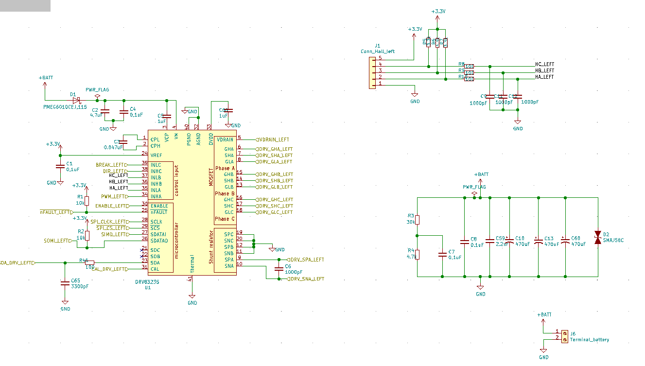
I'm using csd88584q5dc half-bridge power block,

I have the PWM signal in INHA pin, I see it with an oscilloscope, also the hall sensor inputs connected to the corresponding pins in schematic. I'm using 24V as VM.
I based my design on TIDA-00774 and TIDA-01516, I'm not an expert in the motor drivers field and I can realize there are lot of concepts and information I don't know,
Is the configuration I'm using ok? Any help would be really appreciated. Thanks in advance.
Diana


