This thread has been locked.

If you have a related question, please click the "Ask a related question" button in the top right corner. The newly created question will be automatically linked to this question.

CCS/DRV8350H-EVM: Getting USB interfaces loaded on new board based upon DRV8350H EVM board design.

Part Number: DRV8350H-EVM
Other Parts Discussed in Thread: MSP430F5529, MSP430F5528, DRV8350, MSP-GANG, UNIFLASH, MSP-FET

Tool/software: Code Composer Studio

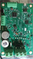
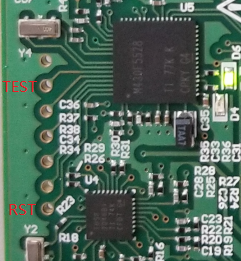
Have fabbed a board based upon the DRV8350H-EVM adding an interface, the usb shows up only as:

"T:  Bus=03 Lev=01 Prnt=01 Port=10 Cnt=01 Dev#= 62 Spd=12   MxCh= 4
D:  Ver= 1.10 Cls=09(hub  ) Sub=00 Prot=00 MxPS= 8 #Cfgs=  1
P:  Vendor=0451 ProdID=2046 Rev= 1.25
C:* #Ifs= 1 Cfg#= 1 Atr=a0 MxPwr=100mA
I:* If#= 0 Alt= 0 #EPs= 1 Cls=09(hub  ) Sub=00 Prot=00 Driver=hub
E:  Ad=81(I) Atr=03(Int.) MxPS=   1 Ivl=255ms

How do I get the usb interface for tools and downloads, as well as the "Product=MSP430-USB Example" interfaces loaded?

T:  Bus=03 Lev=02 Prnt=40 Port=01 Cnt=02 Dev#= 45 Spd=12   MxCh= 0
D:  Ver= 2.00 Cls=ef(misc ) Sub=02 Prot=01 MxPS= 8 #Cfgs=  1
P:  Vendor=2047 ProdID=0013 Rev= 2.00
S:  Manufacturer=Texas Instruments
S:  Product=MSP Tools Driver
S:  SerialNumber=3697425126001E00....
 and:

Bus=03 Lev=02 Prnt=40 Port=00 Cnt=01 Dev#= 46 Spd=12   MxCh= 0
D:  Ver= 2.00 Cls=02(comm.) Sub=00 Prot=00 MxPS= 8 #Cfgs=  1
P:  Vendor=2047 ProdID=0300 Rev= 2.00
S:  Manufacturer=Texas Instruments
S:  Product=MSP430-USB Example
S:  SerialNumber=57748A6E31001800
C:* #Ifs= 2 Cfg#= 1 Atr=80 MxPwr=100mA
I:* If#= 0 Alt= 0 #EPs= 1 Cls=02(comm.) Sub=02 Prot=01 Driver=cdc_acm
E:  Ad=81(I) Atr=03(Int.) MxPS=  64 Ivl=255ms
I:* If#= 1 Alt= 0 #EPs= 2 Cls=0a(data ) Sub=00 Prot=00 Driver=cdc_acm
E:  Ad=02(O) Atr=02(Bulk) MxPS=  64 Ivl=0ms
E:  Ad=82(I) Atr=02(Bulk) MxPS=  64 Ivl=0ms

  • More on the above:

    Am on Linux 18.04, lsusb for new board only shows TI Hub,

    CCS cannot connect TIi MSP430 USB1, has error: Error initializing emulator: No USB FET was found

    Same for USB2, USB3...

    How can I get connected with only the TI Hub showing up:

    lsusb shows only TI Hub:

    Bus 003 Device 070: ID 0451:2046 Texas Instruments, Inc. TUSB2046 Hub

    Appreciate suggestions on how to get the initial CCS download going.

  • Maybe you can try to install: first to see if it can help.

  • Have managed to get :

    lsusb: on linux

    Bus 003 Device 010: ID 2047:0200 Texas Instruments MSP430 USB HID Bootstrap Loader
    Bus 003 Device 009: ID 0451:2046 Texas Instruments, Inc. TUSB2046 Hub

    loaded BSL_Scriptor: ./bsl-scriptor-linux-64  script_5xx_usb.txt

    result:BSL Scripter 3.4.0.1

    PC software for BSL programming
    2021-Jan-27 14:14:44
    ---------------------------------------------------------
    Input file script is : /home/joe/ti/BSL-Scripter/ScriptExampleLinux/5xx_usb/script_5xx_usb.txt

    //
    //Script example 5xx USB BSL
    //Device tested: MSP430F5529
    //
    //Download a blink LED application
    //to the device through the USB BSL
    //
    LOG
    ////////////////////////////////////
    //Write RAM USB BSL to the device
    ////////////////////////////////////
    MODE 5xx USB
        Unable to open the HID device

    How do I get more information on the problem opening the HID device; should have found:

    Bus 003 Device 010: ID 2047:0200 Texas Instruments MSP430 USB HID Bootstrap Loader

    Thanks... Joe

  • Hi Joe,

    1.Have you make CCS to connect to MSP430 successfully?

    2. It seems that you are trying to use BSL_Scptor to program the device through USB BSL. 

    Eason

  • Eason,

    I have connected CCS to EVM boards, However, this is a new board based on the EVM design with a new interface and need to download the bootstrap loader which CCS connects to.

    According to documentation, with 3.3V of the USB to PUR pin, the BSL will be activated, which is the case.  Now having problem with "bsl-scripter-linux-64" not finding the BSL, which is at:

    Bus 003 Device 010: ID 2047:0200 Texas Instruments MSP430 USB HID Bootstrap Loader.  Need more information as to why.

    The BSL-scriptor should see the BSL at ID 2047:0200, but doesn't.

    Any suggestions?

  • Hi Joe,

    I am not quite familiar with this part. I will refer to my colleague.

    Eason

  • Hi Joe

    Does the Linux can find the MSP430 USB device when you trigger the USB BSL?

    Best regards

    Gary

  • Gary,

    Status is that the Bootsrap loader shows up as required at ID 2047:0200 Texas Instruments MSP430 USB HID Bootstrap Loader.

    We have rebuilt the bsl_scriptor on linux 18.04, with hid.o from the libusb area of hidapi.  Now get only the following when running the 5xx script:

    ---------------------------------------------------------
    BSL Scripter 3.4.0.1

    PC software for BSL programming
    2021-Feb-05 11:29:17
    ---------------------------------------------------------

    Log mode is turned on!
    ../../Source-Linux/bsl-scripter-linux-64_libusb script_5xx_usb
    Verbose is turned off!

    and the program exits, without error.  Is at the " MODE 5xx USB" line in the script, we think.

    However, the program hidtest_libusb in "ThirdParty/hidapi/hidapi-hidapi-0.8.0-rc1/hidtest/" finds the device:Device Found
      type: 2047 0200
      path: 0003:0059:00
      serial_number: (null)
      Manufacturer: (null)
      Product:      (null)
      Release:      109
      Interface:    0
    So, now need to debug why the scripter crashes trying to open the device, either at the hid_init() or trying to get the device.

    Any help is appreciated.

    Had problem building scripter program, couldn't find any specific documentation on build steps, so the problem may be we didn't properly build the program.

    Thanks, Joe

  • Gary,

    I have rebuilt the bsl_scripter and had success, but need the USB drivers onto the MSP430F5529 that communicate to the CCS, that show up as:

    P:  Vendor=2047 ProdID=0013 Rev= 2.00
    S:  Manufacturer=Texas Instruments
    S:  Product=MSP Tools Driver

    Without this BSL_USB interface running, CCS can't communicate via USB, as best as I can tell.

    Where can I get this?

    Have already downloaded the /MSP430BSL_1_02_00_01 complete bootstrap loader source, but it does not refer to anything that reflects the ProductID: 0013.

    Thanks for the help.   Joe

  • Gary,

    Can we download the firmware from our DRV8350H-EVM with the BSL-Scripter program.  I think we need the existing password(file) to access and read the firmware to copy down to the new board.  Can you provide the password, or can we read the firmware without the password file?

    We don't want to lose one of our development boards by erasing the ez-lite firmware by mistake on the EVM eval board.

    Have downloaded the ez-lite with a lot of other, but that assumes we are building a MSP430 board to talk with our existing board.  Need the ez-lite emulator to run on our board, like it does on the DRV8350H-EVM board in order to continue our development. 

    We are adding an interface that provide for precision pointing within approximately 32 arc-sec for a Brushless DC Motor for precision telescope pointing.

    Appreciate the help,  Joe

  • Hi Joe

    The password file is must be used to unlock the BSL. The BSL-Scripter should have demo .txt file for it it should be named pass32_default.txt or pass32_wrong.txt the contents like this

    @FFE0
    FF FF FF FF FF FF FF FF FF FF FF FF FF FF FF FF
    FF FF FF FF FF FF FF FF FF FF FF FF FF FF 00 00
    q

    Best regards

    Gary

  • it is better to put BSL-Scripter.exe, script_file.txt, pass32_default.txt and imagename.txt into the same folder. And should modify the script_file.txt based on your file's name. You can take script_5xx_usb.txt in the folder "BSL-Scripter\ScriptExampleWindows\5xx_usb"(This is in windows) as an example if you want to use USB BSL and modify it based your condition. If you don't know how to modify it, let me know.

  • One more question here

    Do you use the x86 intel CPU to run the Linux right? I try it in an ARM Cotex-A8 with Debian but it seem can't run the install file.

  • Gary,

    Yes, am using Ubuntu 18.04 an Intel chip.  Yes, there is a problem in the Makefile.  Ends up the program name in the -o pgmName argument ends up being null because the system call fails.  Can supply details of that in another reply.  Will do.

    Regards,  Joe

  • Gary,

    See "MSP430F5529: Building bsl_scripter on Linux 18.04".  To sum up, need to define/set a few variable either as  passed in when calling make or in the Makefile.  Here is the working Makefile:

    ....

    LIBTHIRD := ./ThirdParty/lib64
    LIBDIRS := -L$(LIBTHIRD)
    OUTPUT := bsl-scripter-linux-64_libusb

    ######Added/Changed:  setting the PLATFORM, since $(shell uname -s) doesn't seem to work.  Add defines of BIT64, etc.
    #PLATFORM := $(shell uname -s)
    PLATFORM = Linux
    CMT = "None happened"
    BIT64 = 64
    STATIC = 1
    ######Done added...
    ifeq ($(PLATFORM),Linux)
            CMT = "Coming Through PLATFORM==Linux: $(PLATFORM)"
            CXX:= g++

            ifdef BIT64
            CMT += " BIT64 Defined"
            OUTPUT := bsl-scripter-linux-64-libusb
            endif

            ifdef BIT32
            CXXFLAGS += -m32
            LIBTHIRD = ./ThirdParty/lib
            LIBDIRS = -L$(LIBTHIRD)
            OUTPUT := bsl-scripter-linux-32
            endif

            DEFINES += -DUNIX

            ifdef STATIC
            CMT += " STATIC defined.."
            STATIC_LIBS += -lusb-1.0
            else
    ...

    This compiles on Ubuntu 18.04 and generates the "OUTPUT" file.

    Hope that helps.  Happy to answer any other questions.

  • Gary,

    One more item:  In the link step there is an include of "hid-libusb.o", but in building the hidapi layer, no hid-libusb.o is generated.  Somewhere in the hidapi non-documentation is a note that only "hid.o" multiple are built, and not hid-libusb.o.  You will find in looking at all hid.o's in the hidapi tree, one is int the /lib/libusb or some such directory.  I did a copy of that hid.o into ../ThirdParty/lib64/hid-libusb.o in the process, renaming to prevent confusion.  Then the Makefile does work ok.

    Just sayin... If only the README.txt reflected some of this.

    Thanks.   Joe

  • Gary, HELP:  loading the EZFET_LITE_Rev1_1_FW_3_3_0_6.txt via the scripter and we get:

    ---------------------------------------------------------
    BSL Scripter 3.4.0.1

    PC software for BSL programming
    2021-Feb-19 17:39:07
    ---------------------------------------------------------
    Input file script is : /home/joe/ti/BSL-Scripter/ScriptExampleLinux/5xx_usb/script_5xx_ld_tools.txt

    //
    //Script example 5xx USB BSL
    //Device tested: MSP430F5529
    //
    //Download a blink LED application
    //to the device through the USB BSL
    //
    LOG
    ////////////////////////////////////
    //Write RAM USB BSL to the device
    ////////////////////////////////////
    MODE 5xx USB
    //gives wrong password to do
    //mass erase in the memory
    RX_PASSWORD pass32_wrong.txt
        Read Txt File  : /home/joe/ti/BSL-Scripter/ScriptExampleLinux/5xx_usb/pass32_wrong.txt
        [ERROR_MESSAGE]BSL Password is error!
    RX_PASSWORD pass32_default.txt
        Read Txt File  : /home/joe/ti/BSL-Scripter/ScriptExampleLinux/5xx_usb/pass32_default.txt
        BSL Password is correct!
    RX_DATA_BLOCK_FAST EZFET_LITE_Rev1_1_FW_3_3_0_6.txt
        Read Txt File  : /home/joe/ti/BSL-Scripter/ScriptExampleLinux/5xx_usb/EZFET_LITE_Rev1_1_FW_3_3_0_6.txt
        Time elapsed of writing 131583 bytes : 4.117 seconds
        Speed of writing data :31.21(kB/s)
    SET_PC 0x4400
    //RX_DATA_BLOCK_FAST RAM_BSL_USB.txt
    //SET_PC 0x2504
    DELAY 4000
        Delay 4000 ms

    Which says it loaded and supposedly is running it, guessing PC: ox4400, have tried PC: 0x4404 also, expecting to get the additional "tools" USB device at ID 2047:0013

    but only get same looking at the usb's:

    lsusb:

    Bus 003 Device 081: ID 2047:0200 Texas Instruments MSP430 USB HID Bootstrap Loader
    Bus 003 Device 080: ID 0451:2046 Texas Instruments, Inc. TUSB2046 Hub

    What should the script be with the scripter to load and run the tools EZFET_LITE_Rev1_1_FW_3_3_0_6.txt

    Should I be loading the EZFET_LITE_Rev1_1_BSL_1_1.txt first, setting the PC to ox1000?  or what?  Was concerned about loading at 0x1000. Isn't that the original location of the BSL?

    Could you provide a good script to load and have the proper EZFET_LITE and getting it running so I can communicate to the CSS?  Couldn't find an example to load and run the EZFET_LITE code from the scripter.

    Thanks much,   Joe

  • Hi Joe

    It seems you can do BSL operation like send password and load image in memory and set PC with the BSL scripter. Here I am wandering is why do you want to download EZFET_LITE_Rev1_1_FW_3_3_0_6.txt? 

  • Gary,

    We need to communicate with the Code Composer Studio with the new board.  We are still doing firmware development for this board, which is the same board as the DRV8350H-EVM with an additional interface for pointing.  We think the EZFET_LITE_Rev1_1_FW_3_3_0_6.txt will communicate with the CCS, but maybe need to download the BSL that is associated(?) with the EZFET_LITE.

    What do we need to download to have the board communicate with CCS?

    From what we have read, we will need to update the BSL with the BSL that accompanies the EZFET_LITE_Rev1_FW, which is loaded at 0x1000, but the existing BSL resides there, so we were worried that downloading that BSL would be a problem.

    So back to basics, how do we download what to start communicating to CCS on our new board?

    Thanks,

    Joe

  • Hi Joe

    I have not see use one MCU as debugger and a target device both time. Why not use a external debugger to do this?

    Best regards

    Gary

  • Please take a look at the DRV8350HEVM TI designed brushless DC motor controller board, designed by TI.  That board has no JTAG interface or UART interface, only a USB interface.  The board is available at the TI website.  This board allows the developer to use the Code Composer Studio(CCS) to interface directly via the USB interface, no other debugger interface required.  A USB device shows up as ID 2046:0013, which generally is the FETEZ-LITE interface which is the "Texas Instruments tools" interface.  Can you discuss this with the DRV8350h-EVM engineers, to see how they accomplished this?

    We based our new board on that design with an additional interface for precision pointing a Brushless DC motor.  So we need to be able to debug on that new board to add the new control software for pointing.

    Hope that helps.

    Regards,  Joe

  • Hi Joe

    For the DRV8350HEVM it include two MSP430 devices: MSP430F5528 and MSP430F5529. MSP430F5528 is used for ez-fet that is the debugger. You can see MSP430F5529 Launchpad  The MSP430F5529 is used for communication with motor driver's GUI and communicate with DRV8350. The ez-fet and the MSP430F5529 use the same USB port bridged by a USB hub. To build your own product you don't need the MSP430F5528 and hub because they are just used for debug. For debug I will recommend to use the debug tool MSP-FET . 

    Best regards

    Gary

  • Hi Gary,

    Thanks for the answer.  We have already have a prototype board fabbed with an additional interface to support precision pointing.  We are using this board to develop the pointing algorithms and controls.  So, basically, we are using this existing DRV8350 design with the new interface for development of the firmware.

    We are presuming we need to get the MSP430F5528 into it's BSL, presumably by tying pin 51, PUR high on power up, then with 5528 BSL showing up at ID:2047:0200 on the USB interface.  Then, downloading FETEZ-LITE with the scripter.  With that, we should be able to communicate via CCS to the board and continue firmware development.  We verified that the 5528 interfaces with the 5529 via UART on the board.

    If you see anything wrong with this approach, please let us know.

    Appreciate your looking into this.  If we succeed, we will close this.

    Thanks much,    Joe

  • Hi 

    So you mean there is no code in the MSP430F5528?

    If so you can also try this GUI located at  .....\USB\MSP430USBDevelopersPackage_5_20_06_02\Host_USB_Software\Python_Firmware_Upgrader 

    https://www.ti.com/tool/MSP430USBDEVPACK#downloads 

  • Gary,  I did reply, must have gotten lost in the upgrade of the site;

    Exactly, there is no code in the MSP430F5528, just the BSL.  Will try your suggestion. 

    Have had a problem using scripter application, as noted above, loading to the MSP430F5528.  What should be the entry point for FETEZ-LITE be; 0x4400, 0x4404, 0x1800 or what?  Can't find documentation on entry points.  Have toasted one development board trying to load FETEZ-LITE so need to know what the entry point should be here before trying another dev board.

    Need to be testing our pointing algorithms soon.  So thanks.

    Any help appreciated.  Regards,  Joe

  • More... 

    Gary, we jumpered PUR high on the MSP430F5528, so we have the BSL up on the FETEZ-LITE host device, ready to download.  Have downloaded your suggestion. 

    Will advise.  Regards,  Joe

  • Gary, getting really close here.  On the DRV8350HEVM board, the USB is isolated from the rest of the circuitry, had to also tie the USB ground to the board circuit ground, tie in to the 5528 PUR via 100 ohm and 5V from the USB to get the BSL of the 5528 up.  Then, using your suggested Python firmware upgrader, trying to upload either the EZFET_LITE_Rev1_1_BSL_1_1.txt or EZFET_LITE_Rev1_1_FW_3_3_0_6.txt get the following error:

    Opening HID device HID device (vID=0x2047, pID=0x0200, v=0x0109); Unknown manufacturer; @input.inf,%hid_device_vendor_defined_range%;HID-compliant vendor-defined device, Path: \\?\hid#vid_2047&pid_0200#7&75f911c&0&0000#{4d1e55b2-f16f-11cf-88cb-001111000030}
    Mass erase...
    Download full BSL...
    Programming...
    Programming: OK
    Waiting for BSL...
    closing HID device
    Closed!...
    Opening HID device HID device (vID=0x2047, pID=0x0200, v=0x0109); Unknown manufacturer; @input.inf,%hid_device_vendor_defined_range%;HID-compliant vendor-defined device, Path: \\?\hid#vid_2047&pid_0200#7&75f911c&0&0000#{4d1e55b2-f16f-11cf-88cb-001111000030}
    Programming...
    Exception in Tkinter callback
    Traceback (most recent call last):
      File "C:\msp430usb\msp430_usb\src\python_firmware_upgrader\build\pyi.win32\Python_Firmware_UpgraderGUI\out00-PYZ.pyz\Tkinter", line 1470, in __call__
      File "<string>", line 278, in selectFile
      File "<string>", line 186, in doLoad
      File "C:\msp430usb\msp430_usb\src\python_firmware_upgrader\build\pyi.win32\Python_Firmware_UpgraderGUI\out00-PYZ.pyz\msp430.target", line 259, in program_file
      File "C:\msp430usb\msp430_usb\src\python_firmware_upgrader\build\pyi.win32\Python_Firmware_UpgraderGUI\out00-PYZ.pyz\msp430.bsl5.bsl5", line 172, in memory_write
      File "C:\msp430usb\msp430_usb\src\python_firmware_upgrader\build\pyi.win32\Python_Firmware_UpgraderGUI\out00-PYZ.pyz\msp430.bsl5.bsl5", line 79, in BSL_RX_DATA_BLOCK_FAST
      File "C:\msp430usb\msp430_usb\src\python_firmware_upgrader\build\pyi.win32\Python_Firmware_UpgraderGUI\out00-PYZ.pyz\msp430.bsl5.hid_1", line 66, in bsl
      File "C:\msp430usb\msp430_usb\src\python_firmware_upgrader\build\pyi.win32\Python_Firmware_UpgraderGUI\out00-PYZ.pyz\msp430.bsl5.hid_1", line 137, in write_report
      File "C:\msp430usb\msp430_usb\src\python_firmware_upgrader\build\pyi.win32\Python_Firmware_UpgraderGUI\out00-PYZ.pyz\pywinusb.hid.core", line 513, in send_output_report
    AssertionError

    Should I catenate the two txt files, as suggested in the documentation, then load the FETEZ..BSL with the FETEZ..FW from a single file?

    Can get to the 5528 BSL, but apparently has a problem loading the .txt file;  Suggestions? 

    Help appreciated,  Regards,  Joe

  • Gary, got around previous error: just loaded txt file from a subfolder, and the downloader worked.  Now have a USB device at 2047:0013 that the CCS gets an error: "MSP430:  Error initializing emulator:  Could not set device Vcc", but the CCS now sees FETEZ-LITE.  Since the EZFET_LITE_Rev1_1_BSL_1_1.txt is not loaded with this, will try the catenation of this file with the EZFET_LITE_Rev1_1_FW_3_3_0_6.txt and download that.  Maybe needed both to run properly... Might be wishful thinking.

    Getting closer still.  Any idea about the CCS error of "Could not set device Vcc" ?

    Regards,  Joe

  • Gary,

    Catenated the EZFET_LITE_BSL+EZFET_LITE_FW files, removing "q" line as suggested in documentation.  Downloaded ok with the Python application.  CCS tries to connect but results in same "MSP430:  Error initializing emulator:  Could not set device Vcc" error.  The HID VID: 2047:0013 comes up fine, so the version of EZFET_LITE_FW is up ok.

    So, we think we need link to the MSP430F5528 EZFET_LITE_FW firmware used on the TI DRV8350HEVM evaluation board, so we can talk to the Code Composer Studio with our development board.

    Can you get me a link or a copy of that firmware.  Probably customized to run on the DRV8350HEVM evaluation board.

    Or if I have a hardware problem on our new board, need some clue as to what to look for.

    Done all we can do for firmware development using the DRV8350HEVM we have, need to add in and test our control algorithms on the new board.

    Thanks, Joe

  • Hi Joe

    What's the EZFET_LITE_BSL? Remember although EZFET_LITE_BSL+EZFET_LITE_FW are located at different flash memory two critical things here need to be figure out:

    1. How to switch between the two firmware 

    2. Every firmware have different interrupt vector, how you deal with them?

    3. The two project will share the same SRAM? If so it will crash the SRAM.

  • Gary,

    The EZFET_BSL is contained in the same directory the EZFET_LITE_FW from TI.  Thought it should be loaded first or used to load the EZFET_LITE_FW.  Didn't think they should be run together.  Thought that the EZFET_LIT_FW should be loaded second and run, if it needed to have the BSL.  The EZFET_LITE_FW was loaded solely and shows up at USB DevID: 2047:0013 as it should and the CCS begins communicating with it with the error as indicated above.

    Meanwhile, chasing hardware problems on new boards.  Can load our firmware on the 5529, can't use the CCS for debug, so have added debugging into our application and our application specific GUI program.  If we get a break, then maybe will be able to connect CCS successfully.  Still get the "MSP430:  Error initializing emulator:  Could not set device Vcc" error.

    We are working around not having CCS for debugging for the moment.  Wish we didn't have to.

    Any suggestions are appreciated.   Joe

  • Hi Joe

    For USB devices we will pre-download a USB BSL in the BSL flash memory located at 0x1000 to 0x17FF. More information about that.

    That means you don't need to download it.

    For the EZFET_LITE_FW could you show me where you download it?

  • The EZFET_LITE_FW came from:

    eZ-FET_lite_Release_Package_rev_1_10_20130712/eZ-FET lite rev 1.10 Release Package/Firmware/EZFET_LITE_Rev1_1_FW_3_3_0_6.txt

    Seems to run OK, Still get the "MSP430:  Error initializing emulator:  Could not set device Vcc" error from connecting and attempting to download from the CCS development environment.  If we knew what the error is telling us, we might be able to chase the problem.

    Thanks for the help.

    Best Regards,  Joe

  • Two more comments from my side

    1. make sure you download the EZFET_LITE_FW in MSP430F5528

    2. Make sure the voltage detection hardware is designed in your board

  • Gary,

    1.  We are sure we loaded the EZFET_LITE_FW in the MSP430F5528.  We have our application running on the MSP430F5529, using the PUR held high originally on each seperately to load the EZFET and our application.

    2.  Will double check the circuitry for proper operation, since we didn't change the design on the DRV8350HEVM evaluation board in this area, except to add an interface.

    Will advise as to results.  We seem to be having a problem with the 25 kilohertz timer function; why we don't know yet.  USB interface works fine, meaning that the application itself is running ok, but don't get any PWM outputs from the MSP430F5529.  Hall effect inputs were flakey at first, but after probing around and adding tracing to the app to verify hall inputs, seems to be ok.  So, the commutation is operating.  Now to get the motor control PWM stuff working and we will be doing fine.

    Would be easier with the CCS working.

    Thanks for the circuit above.

    Regards,  Joe

  • Hi Joe

    You can try to use this image that I have read from the MSP430F5529 launchpad.

    Target_m.txt

  • Gary, we tried the suggested image, with the same results "MSP430:  Error initializing emulator:  Could not set device Vcc" from the Code Composer Studio.

    Checked the circuitry as above on our board, get the same volt readings at pin 1 and pin 2 as the original EVM board.

    Should the image be from a "MSP430F5528 Launchpad" instead of the MSP430F5529?

    Thanks for the image to try.  Any other suggestions will be appreciated.

    Is there a way to tell CCS to bypass checking device VCC?

    Sorry about delay... were working other issues and contending with COVID.

    Regards,   Joe

  • Sorry about the delay of the labor day holiday. 

    That is so weird that if the hardware and software are both same the device is not working. The image contain some date located at info-memory have you enable download info-memory when you try to download the image? You can try to read out the image to see if you download the total image successfully. 

  • Not so weird, since we only can get EzFETLite image built for the MSP430F5529, not the MSP430F5528, which is the "EzFETLIST" processor on the DRV8350H-EVM.  There are differences between the 5528 and 5529 we are guessing that could make the difference in getting the VCC or not.

    Where is the source code to EzFETLite, so we can check for header files that could be set up for building a MSP430F5528 version of EzFETLite? 

    The /eZ-FET_lite_Release_Package_rev_1_10_20130712 doesn't have the source, only source for test programs.  The test programs do include of "#include <MSP430F5528.h>", so maybe the 28 is the basis.

    Any help here is appreciated.  Problematic doing development without a CCS connection.

    Is there a more direct connection to technical support for the DRV8350H-EVM evaluation board.  Mentioned our problem to my brother(long time EE) who just laughed.

    Regards,  Joe

  • The image I send to you is read out from MSP430F5528 that is part of eZ-FET lite.The image is production version and works well in the MSP430F5529's launchpad, so the image is no problem. 

    I am confusion what hardware you have used to do the test, could you share me some pictures of the hardware and the schematic to me and let me verify it?

  • Gary, here is the image of the board.  Same circuit as the DRV8350H-EVM, with added interface to three signal lines coming from the top, to P1.1(pin 22), P1.7(pin 28) and P2.2(pin30) of the MSP430F5529.  These are low voltage signals coming from an optical encoder, powered by 5V, coming into open collector drivers(U12,U13) with 3.3V pullups(R97,R98,R99).  All the rest of the circuitry is identical to the original.

    I thought that the EZFET)LITE  image you sent came from as above: "You can try to use this image that I have read from the MSP430F5529 launchpad".  We did load the Target_m.txt, which you got from the MSP430F5529 launchpad, not from the MSP430F5528 area.  We get the same error connecting to the CCS.  As you noted above:

    "Two more comments from my side

    1. make sure you download the EZFET_LITE_FW in MSP430F5528

    2. Make sure the voltage detection hardware is designed in your board"

    We think we have not gotten an image EZFET_LITE for the MSP430F5528 as yet.  Can't find one.

    As for 2, we have checked the voltages coming to the 5528, as in circuits above, the voltage is the same on the TI Board as well as our new board, something like 1.6 and 1.8 V respectively going to pin 1 and pin 2 or the 5528.

    Hope that helps.

    Thanks for keeping with this.

  • Hi Joe

    Do you have a DRV8350H-EVM on your side? Dose it works? If not I can apply one to check if it works on myside.

  • Gary,

    We have a working DRV8350H-EVM from TI.  We don't want to try loading any EzFETLite image we have gotten so far, which might take it out of service.  We can't find a way to read out the image on the 5528, since not knowing the password will cause a mass erase, then we have no working board that CCS can access.

    If you have a way to download the EzFETLite image from your DRV8350H-EVM from the 5528, that would be wonderful.

    Meanwhile, we will continue stumbling along.  We know that images we build on CCS,, then generate the ti.txt formatted file and downloading with the PythonLoader or whatever works.  We then have a little gui to read trace info down from the running image on the new board.  Slow going, but we've seen worse.

    If we can finally get CCS to connect to the new board, we will be forever grateful.

    Regards,  Joe

  • Hi Joe

    Have you see the test port near the MSP430F5528 at below?

    You can see the board have layout the debug port for MSP430F5528 with the JTAG interface. You can use this port to download the MSP430F5528's image.

    We can't find a way to read out the image on the 5528, since not knowing the password will cause a mass erase,

    We can use the JTAG interface to read out the image on the F5528 with out password. The BSL need the password for access.

    If you have a way to download the EzFETLite image from your DRV8350H-EVM from the 5528

    We can use the JTAG interface to download the image.

  • Gary,  Thanks.  What tool do you recommend we get to interface here? Will get on order.   Also, what program to use to download the image? On windows 10 or Linux, either one... presumably not CCS.

    This should work!

    Regards,  Joe

  • What tool do you recommend we get to interface here?

    You can use an eZ-FET(Every MSP430 launchpad will include this), MSP-FET or MSP-GANG.

    what program to use to download the image? On windows 10 or Linux, either one... presumably not CCS.

    Lots of software can be used. Like CCS, IAR, Uniflash, Lite FET-Pro430 and so on. They should support both windows and Linux.

  • Gary,

    Ordered the MSP-FET emulator, should be able to hook into JTAG, on the DRV8350H-EVM.

    Question is what tool is best for uploading the ezFET-lite firmware already loaded on the DRV8350H-EVM board on the MSP430F5528?  ... the CCS, IAR, Uniflash...  Didn't see on CCS ability to hook into an MSP430 device and upload(upload, meaning upload from the MSP430) the firmware to an image file.  Don't want to lose the working board. Your suggestion would be appreciated.  We assume the memory map is equivalent to that we see in the EZFETLITE memory map for the MSP430F5529; i.e. Loading starting at @1800, then continuing at @4400?

    Best Regards,  Joe

  • Gary,

    We don't see a way to upload an image from memory of the MSP430F5528 with CCS without downloading a project, which destroys what is already there.  Can't read memory without connecting and downloading for debug.  No reference to uploading from a device by just connecting.  Are we missing something?

    Apparently IAR does have a "connect without downloading" feature.  Does Uniflash, Lite FET-Pre430 or any others allow connecting and reading from the MSP430F5528 without destroying what is already there?

    If you have a DRV8350H-EVM and could test generating the ti.txt image of what is running on the MSP430F5528(EZFETLite host processor), let us know how to accomplish that. If you can please forward directions or even a ti.txt image file.  We need to be able to do this.

    Thanks so much, Joe

  • Gary,

    We see that with an AlternateConfiguration in CCS, we can have a GEL script that connects without downloading.  Can't find a GEL file that reflects such. 

    Once connected, using GEL we should be able to upload memory blocks to a hex file so we can generate a suitable ti.txt file to load on the new board.  Great.

    Can you supply a CCS example GEL file that connects without downloading?

    Thanks for your help,

    Regards,  Joe

  • Question is what tool is best for uploading the ezFET-lite firmware already loaded on the DRV8350H-EVM board on the MSP430F5528? 

    If you have ordered MSP-FET, I am recommend to use Lite FET-Pro430 GUI software in PC to read the image.