This thread has been locked.

If you have a related question, please click the "Ask a related question" button in the top right corner. The newly created question will be automatically linked to this question.

DRV8320: Unsure about regenerative braking in 1x PWM mode?

Part Number: DRV8320
Other Parts Discussed in Thread: INA202

Hello Engineers,

I'm designing a 60A BLDC controller around the DRV8320 and the Raspberry Pico. As a means to simplify the firmware I choose the 1xPWM mode.

Open Source design files on Oshpark (link). 

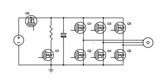
The image above shows a simplification of the schematic. Q1-Q6 are controlled by the DRV8320 while Q7 and Q8 are controlled by the Raspberry Pico. 

From what I can fathom I have three ways to brake:

1. Using the DRV8320 brake pin, which opens Q2, Q4 and Q6

2. Using resistive braking, put the direction pin in reverse while closing Q8 and opening Q7

3. Regenerative braking, put the direction pin in reverse while keeping Q8 open. Monitor the bus voltage and open Q7 (and close Q8) when the voltage exceeds a threshold. 

Am I correct in the assumption that I need to put the direction pin in reverse while still applying a PWM?

What effect does the PWM duty-cycle have on the regenerative braking? 

  • Hi Roy,

    Thank you for your question! I will try to respond to your question tomorrow.

    Regards,

    Anthony

  • Hi Roy,


    I just wanted to start off making sure we are clear regarding terminology: for the purpose of this discussion “closing” a MOSFET means that the MOSFET is no longer conducting, and “opening” a MOSFET means that the MOSFET is now conducting.

    When you put the direction pin in reverse the driver will try to create a current to spin the motor in the opposite direction, but this current will be opposed by the current already flowing in the motor. This results in a quicker decay of the current in the motor (thus allowing for quicker breaking), but also produces a larger back emf which must be watched carefully so as to not exceed the abs max ratings of the device. The PWM duty cycle will affect the amount of current that is supplied to oppose the current flowing in the motor, and thus will affect the speed that the motor comes to a stop. A higher PWM duty cycle results in a higher average voltage, and therefore a higher average current that apposes the current already flowing through the motor. A lower duty cycle results in a lower average voltage and thus a lower average current to oppose the current already in the motor.

    One thing to be very careful about is that if you were to suddenly reverse the direction of the motor and apply a high opposing current to the current in the motor, that will result in a large back emf that could rise very rapidly, possibly too quickly for the bus voltage monitoring circuit to react in time to isolate the voltage supply and open the resistance path. This could lead to a violation of the abs max ratings of the device and could cause a lot of damage. I would recommend starting with a low PWM duty cycle to ensure that your bus voltage monitoring circuit has time to react to changes in the voltage.


    One thing to keep in mind for regenerative breaking is that it would be necessary to have a threshold so that once the bus voltage drops below a specific voltage then Q8 would be opened again and Q7 would close. This would prevent an undervoltage event from occurring on the bus voltage since the power supply is cut off when Q8 is closed and VM is only supplied from the current drop through the resistor, as well as the voltage that is stored in the bulk capacitors in your circuit.      

    Regarding your 2nd method of breaking, the main issue with that method is that by closing Q8 and only relying on the resistor, the bus voltage will begin to drop as the current decays since the voltage is only generated by the current across the resistor. This will eventually lead to an undervoltage fault on the bus voltage.

    Regards,


    Anthony

  • Hello Anthony,

    Thank you for your reply. I'm happy to see I was almost on the right track.

    A Raspberry Pico running micropython can be quite slow to act in case of the overvoltage situation. I think I'll put a comparator as as overvoltage protection connected to the gate of Q7. In almost the same way I used an INA202 as overcurrent protection on Q8 in my non-simplified schematic. 

    An undervoltage will be less likely in my situation as I'll be using a 10S lithium-ion battery with a minimum voltage of about 30V. This gives the Pico a lot of time to react until VM reaches 6.0V. 

    I learned a lot from your reply!

  • I am glad I could help you! Please don't hesitate to reach out to us if you have any other questions. Have fun spinning motors!

    Regards,

    Anthony