This thread has been locked.

If you have a related question, please click the "Ask a related question" button in the top right corner. The newly created question will be automatically linked to this question.

DRV8876N: Charge Pump Undervoltage Lockout

Part Number: DRV8876N

Hello;

I've set up a circuit using the DRV8876N Motor Driver, but upon testing have found that the chip is not operating and the fault indicator is showing a fault condition.

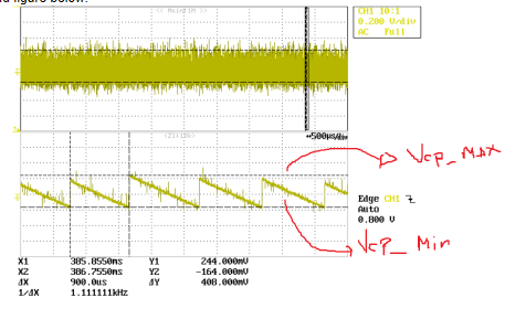
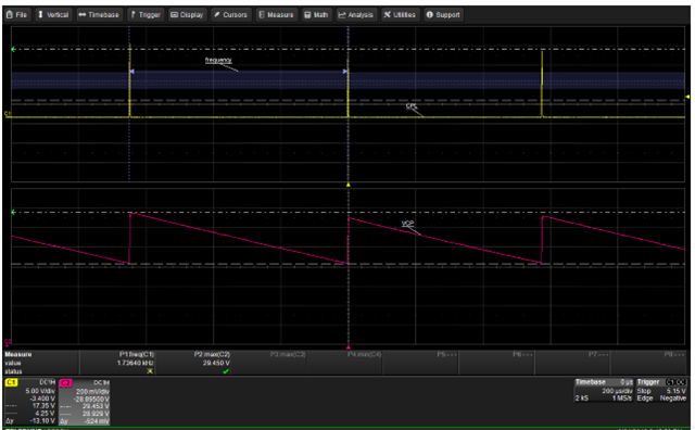
According to the data sheet, the fault indicator will show a fault condition when VCP pin is less than 2.25 V with respect to VM. Upon investigation I've found the VCP pin is exhibiting a sawtooth waveform from 0.8V less than VM to 0.8V more than VM. Can you please provide assistance in correcting this issue?

VM is 11.6V

VM to GND bypass capacitor - Parallel 0.1uF 100V C0G and 10uF 25V X5R ceramic capacitors

VCP to VM charge pump storage capacitor - 0.1uF 100V C0G ceramic capacitor

Charge pump flying capacitor (connecting CPH to CPL)  - 0.022uF C0G ceramic capacitor

Thanks

Jeremy

  • Hi Jeremy,

    Thank you for posting to the forum.

    Can you provide a waveform of VCP, VM, and nFAULT?

  • Hi Pablo;

    I didn't record the VM or nFAULT waveforms when I had the opportunity by can advise that the VM pin was sitting at 11.6V and the nFAULT pin was pulled to 0V.

    VCP's waveform when provided a 100kHz square wave with a 50% duty cycle on one input is at the below link:

    https://www.dropbox.com/s/6jzjbdx7um0a7l6/VCP%20Waveform.jpg?dl=0

    P.S. I'm unsure if this is relevant to the issue but the configuration is in Independent Half-Bridge Control Mode (i.e. PMODE pin floating).

    Thanks

    Jeremy

  • Hi Jeremy,

    Thank you for providing the waveform. The sawtooth waveform is expected for VCP. below is a quick explanation of how the charge pump functions. My guess for why the VCP voltage is low is either the charge pump capacitor is damaged or shorted. Can you replace both of the capacitors? If that does not work, can you replace the driver with a new one? If replacing the driver fixes the issue, it could mean that the device was damaged somehow.

    Charge pump ripple:

    This ripple behavior of the charge pump is to be expected. There is a min (Vcp_min) and max (Vcp_max) values for the charge pump. The charge pump will only charge when needed (Vcp getting closer to minimum value) and then discharge when Vcp hits the maximum value (This is to prevent damaged to the device from overcharging the Vcp). The time it takes to discharge depends on many factors such as the Vcp capacitance, leakage current, and more. There is an internal comparator which constantly checks that the Vcp is within bounds. 

    Usually, the difference between Vcp_min and Vcp is around 400mV but can vary. The device is designed such that the difference does not affect its performance. 


    The CPL will dump its charge to VCP only for brief moments (enough to charge the Vcp to the max value) and stop dumping charge until Vcp hits min value) This repeats in a periodic manner and its frequency will define the frequency of the ripple. (As shown in the second figure below.


  • Thanks for your help Pablo;

    I can try replacing the driver, the charge pump storage capacitor and the charge pump flying capacitor however I doubt that the issue is a damaged component as I've repeated this circuit 5 times across my PCB and am seeing the same behavior at each location. If it helps, I've confirmed my circuit replicates figure 19 from the DRV8876N H-Bridge Motor Driver datasheet (except pin 2 PH/IN2 is supplied a PWM waveform in accordance with the Independent Half-Bridge Control Mode scheme)

  • Hi Pablo;

    I've tried replacing the charge pump storage capacitor and the charge pump flying capacitor, as well as the VM to GND bypass capacitors and the Driver. Unfortunately i'm still experiencing the exact same issue. Is there a way to disable the charge pump operation?

    Thanks

    Jeremy

  • Hi Jeremy,

    The only way to disable the charge pump is by placing the device in sleep mode (nSLEEP=0). However, the charge pump needs to be on in order to drive the load. I'm sure you have checked already but is the device awake? what is the voltage at the nSLEEP pin?

  • Hi Pablo,

    These tests have been run with the nSleep pin set to 3.3V. Your right that the charge pump doesn't run, and the fault pin clears, when the device is in sleep mode.

  • Hi Jeremy,

    Since this issue is replicated in all of you're units, I think there might be a circuit or layout issue. Can you share your schematic and layout?

  • Hi Pablo; I believe i've made an error in my selection of capacitors (having replaced the previous components with the same models). I will try the new capacitor values and see if it corrects the fault.

  • Hi Jeremy,

    Let me know if the new capacitors fix the problem.

  • Hi Jeremy,

    Any updates?

  • Hello Pablo,

    Thank you for your assistance, replacing the capacitors has addressed the problem and the units are now working correctly.

  • Hi Jeremy,

    Thank you for the update, I'm glad your units are working correctly now. I'll close this thread since the issue has been resolved.