This thread has been locked.

If you have a related question, please click the "Ask a related question" button in the top right corner. The newly created question will be automatically linked to this question.

DRV8307: Start-UP

Part Number: DRV8307
Other Parts Discussed in Thread: DRV8306

Hi,

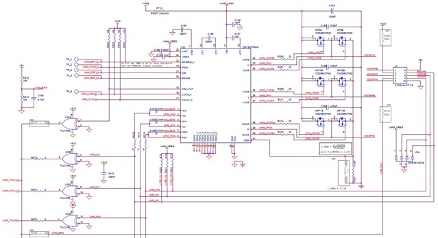
I am using the DRV8307 to control a DPM 57BL74B1 motor at 30V. I drive the controller using ENABLEn and PWM, in a unidirectional way and without using the brake function, i also cut off the power supply (VM), when I'm not using the motor.

My problem is: 

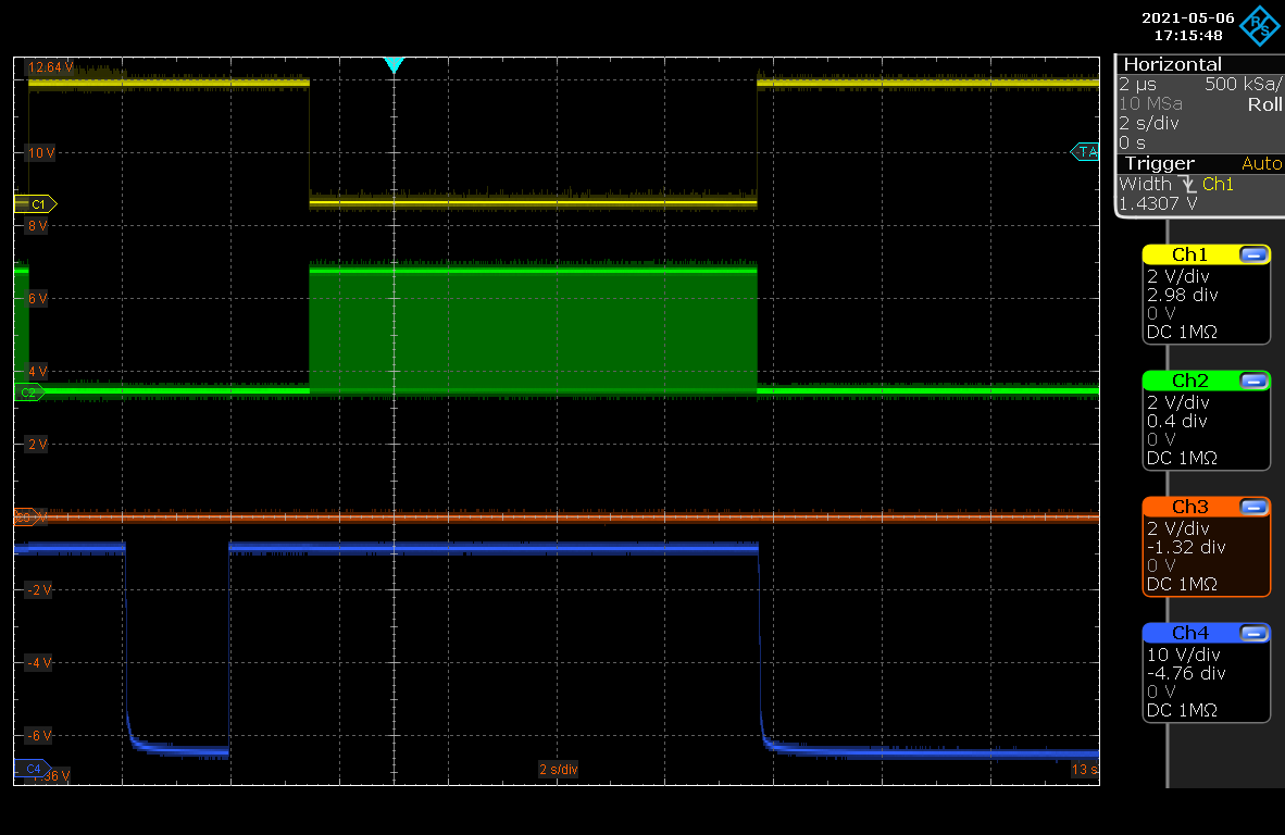
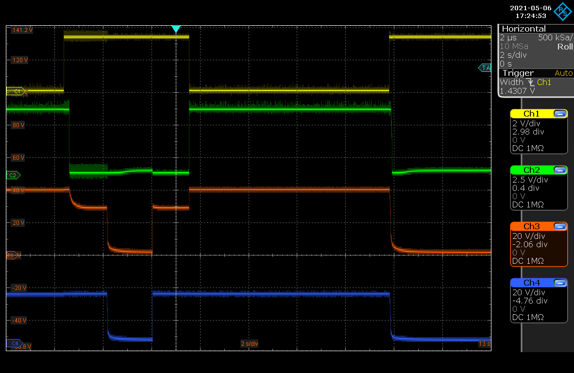
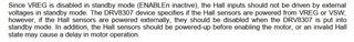
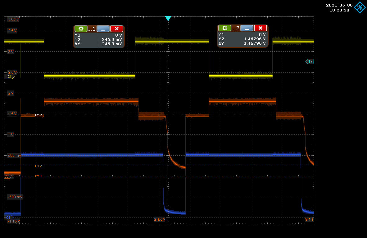
If the time between the shutdown of the VM voltage and a subsequent restart is included in a certain interval, typically between 1-2 seconds (I verified that the VINT drops from 1.8V to about 0.3V and then rises to 1.8V), some samples of DRV8307 will not start correctly , leaving the motor stopped, although the ENABLEn and PWM signals are activated subsequently.

Apparently the internal logic does not seem to have started correctly, in fact the driving of the High-Side and Low-Side FETs do not evolve.

Is there a time specification that can explain this problem ?

It is normal for the VINT to remain at 1.45V, with the VM present and ENABLEn disabled ?

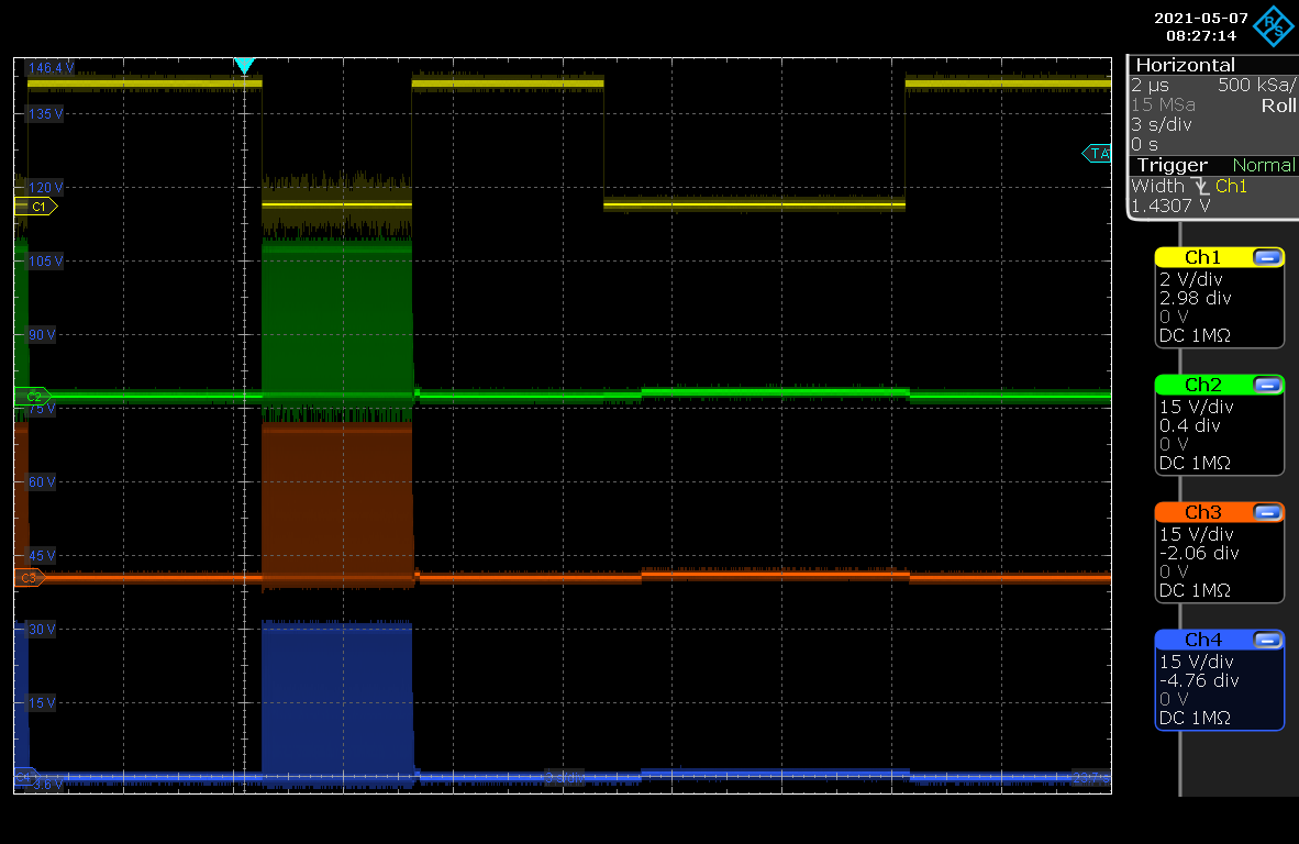
CH1 (Yellow) = ENABLEn (2V / Div.) 

CH3 (Orange) = VINT (0,5V / Div.)

CH4 (Blu) = VM (10V / Div.)

                                                                                                Daniele Bertola

  • Hello Daniele,

    The DRV8307 has logic integrated which will prevent it from starting to spin the motor unless the motor is completely stopped. Therefore when powering up and starting to spin, if the motor is already spinning it will wait until the motor has stopped before starting. The newer version of this IC called DRV8306 does not have this functionality. I'm not sure if this is the exact issue you are having but it does sound somewhat similar.

    • Is the motor completely stopped in this OFF time, or is it still coasting?
    • Does the DRV8307 never start the motor? Or does it eventually start after some time?
    • Is the motor getting stuck in a stall condition on start up? (outputs still driving PWM, but the motor does not commutate)
    • Can you provide an oscilloscope capture of:
      • VM, ENABLEn, PWM, BRAKE
      • VM, ENABLEn, VCP, VREG
      • ENABLE, U, V, W
      • ENABLE, HU+, HV+, HW+
    • Can you share your schematic?

    VINT is an internal regulator, and during sleep the consumption of current is very low. Therefore I would expect that this regulator will hold some voltage.

    Thanks,

    Matt

  • Hello Matt.

    I start with answering the questions.

    -The engine practically stops on the ENABLEn ascent, so this cannot be the problem.

    -The drv8307 never starts the motor.

    -The motor does not stall, the gates of the FETs simply never evolve, and the drives of the High-side FETs are all at 0V

      (UHSG,VHSG,WHSG = 0V).

  • I am attaching two of the required images.

    ENABLEn, PWM, BRAKE, VM

    ENABLEn, VREG, VCP, VM

    In both images the engine was not piloted.

  • Hello Daniele,

    It does look like the VREG and VCP are coming up as expected.

    I see from the schematic that the HU-, HV- and HW- pins are biased with a reference generated from +5V rather than from VREG. There may be some latch up issue if these pins are biased when the DRV8306 is not powered on or in sleep mode. Can you lift the +5V terminal on R310 and blue-wire it to VREG to see if there is any improvement?

    Please see the end of 7.3.1 Hall Comparators from page 11 of the DRV8307 datasheet:

    Thanks,

    Matt

  • Hello Matt.

    I will run the test you proposed to me on Hall's BIAS. In the schematic (which is not my project) also the power supply of the Hall sensors (Pin6 of J7) is in any case linked to the external 5V (always present), so this too should be revised, correct?

    Speaking of latch-up, the fact that the ENABLEn, HALLOUT, LOCKn, FAULTn signals are Pulled up on 3.3V, can it cause problems?

  • I attach image of ENABLEn, U, V, W, as requested.
    You may notice a correct first start of the engine and a second one not performed.

  • I only made the change on the BIAS, but without having positive feedback.
    The electronic board in question still has the defect.


    I will also try to act on the Hall power supply.

  • Considering what is reported in the datasheet, if I piloted the "ENABLE_n" signal always active (0V), and I only shut down the VM, I should rule out the problem, correct?

  • As for the power supply of the Hall sensors, it is true that they are always powered (pin 6 of J7), but their outputs are in open collector, so they do not load the driver, when this is off or in standby.

  • Hi Daniele,

    I will run the test you proposed to me on Hall's BIAS. In the schematic (which is not my project) also the power supply of the Hall sensors (Pin6 of J7) is in any case linked to the external 5V (always present), so this too should be revised, correct?

    As for the power supply of the Hall sensors, it is true that they are always powered (pin 6 of J7), but their outputs are in open collector, so they do not load the driver, when this is off or in standby.

    • Since the hall outputs are open drain, I think the only concern is the output pull-up voltage and whatever is used as the negative reference. The Hall can be powered as long as it is not forcing a voltage onto the DRV8307 pins.

    Speaking of latch-up, the fact that the ENABLEn, HALLOUT, LOCKn, FAULTn signals are Pulled up on 3.3V, can it cause problems?

    • Digital inputs should be OK to drive with voltage, even when the part is in sleep mode, it is only the analog Hall input comparators which appear to have this issue.

    Considering what is reported in the datasheet, if I piloted the "ENABLE_n" signal always active (0V), and I only shut down the VM, I should rule out the problem, correct?

    • Tying ENABLEn low will let the part drive the motor whenever VM is applied (with some delay as the part powers on)
    • Based on the previous results I am not confidant it will fix the issue, but it is worth trying.

    Thanks,

    Matt

  • I performed a test, in which the only variant is the permanent 0V fixing of the "ENABLEn" signal, and during this morning I have not been able to fall into the problem anymore.

    To date I have found two ways to get out of the problem: delay the reactivation of the VM after a shutdown of at least 3 seconds, or leave ENABLEn always at 0V.
    Is there any theoretical confirmation in all this?

    This problem has occurred to date in two drivers on about 1500 PCBs made.

  • Returning to ENABLEn; in our application this signal is kept high not only in sleep mode, but also during the driver shutdown (VM = 0V).

    What should be the correct driving sequence for this signal, starting from switching on the driver to switching off?

  • Hi Daniele,

    Interesting that tying ENABLEn to 0 allows the system to work as intended. This would imply the device is getting stuck in ENABLE power-up in cases where it does not spin properly.

    There is not an issue with holding +5V at the ENABLEn pin when the DRV8307 is unpowered. The pin will prevent current from flowing into the device (with the exception of a pulldown resistance)

    I have a few thoughts and questions:

    • Low occurrence rate implies marginality in the DRV8307 or external components.
    • Noise coupling onto the hall comparator inputs of the DRV8307 causing it to "think" that the motor is still spinning. It will then wait until the noise is gone before starting the motor
      • You should remove C191, C193, and C195. These would only be useful if you had Hall elements rather than Hall sensors with open drain outputs. These components will couple noise onto the hall element comparators whenever the halls switch (HALLBIAS is a relatively high impedance node)
    • Does nFAULT ever go low indicating a fault condition?
    • When shutting down ENABLEn, all of the DRV8307 regulators will stop driving but they may hold charge on the external capacitor (VREG, VINT, VSW, VCP).
      • The regulator may be getting "stuck" or halting operation of the digital core when it is re-activated with some charge left on the capacitor.
      • Add a small leakage path by putting a resistor in parallel with VINT & VREG to ensure they decay to zero during the VM OFF time.
    • Do you know the part number for the Hall Sensor integrated into the motor? We can check for any "sneak path" between +5V and the hall input comparators or VREG.
    • Section 8.1.2 of the datasheet indicates that ENABLEn shutdown will proceed whenever ENABLEn is brought logic high for 1.2us. The driver will then wait for the motor to stop (rotation halted & then wait for 1 extra second) and then power down the regulators. It is important to note that even if you bring ENABLEn logic low during this time, the driver will still go through the whole sequence and shut down.

    Thanks,

    Matt

  • Hello Matt.

    Thanks for the indications.
    In fact, I had already done the test to discharge only the Vint voltage, with a resistance of a few KOhm, and I had been successful, but not being a documented practice I had abandoned the idea; is it achievable ? what value should resistance have?

    The halls inside the engine are marked "8 Honeywell" on one side and "41F 435" on the other.

    I will try the way of eliminating C191, C193 and C195, without touching anything else.

  • Hi Daniele,

    VINT is not intended for external load, however you can reasonably pull 100uA out of it, so an 18k resistor is appropriate.

    This Hall Sensor looks like an SS41F, which is open drain. There won't be any leakage path from the Hall power pin to the output.

    Thanks,

    Matt

  • Hi Daniele,

    Do you need further assistance on this case?

    Thanks,

    Matt

  • Hi Matt.

    For now the problem is so sporadic that we do not intend to intervene in hardware mode, but simply by increasing the delay between shutdown and restart.
    In any case, none of the hardware changes discussed, led to the resolution of the problem.

    Thanks for support.

  • Hi Daniele,

    I'm glad you could find a solution to improve the performance in the system. Please come back if you have further questions.

    Thanks,

    Matt