This thread has been locked.

If you have a related question, please click the "Ask a related question" button in the top right corner. The newly created question will be automatically linked to this question.

DRV8353RH-EVM: DRV8353RH

Part Number: DRV8353RH-EVM
Other Parts Discussed in Thread: DRV8353, CSD19506KTT

Hi

We have designed a motor driver board based on the DRV8353RH-EVM_Sch from TI.

The boards all work fine for low PWM speed demands for forward and reverse rotations of about 500 RPM. We have had them working for several hours at low speed demand.

But when we increase the PWM demand to speed the motor above 500 RPM to 1000 RPM the DRV8253RH chip gets very hot in about 5 seconds and the board stops working permanently. Same is true if we do rapid forward and reverse rotation in this case the DRV8353 chip gets very hot in less than 3 seconds and the board stops working.

We have a fault LED on the fault pin and this comes on. After we power down the board and power up again the fault LED comes on straight away indicating there is a fault.

The damage always seems to be between one of the GLx & SPx pins which shows a resistance of less than 10R (should be 140K according to the datasheet). We measured this with the Mosfet de-soldered off the board, because at first we thought the Mosfet had gone short circuit but this is never the case.

We have checked the Mosfet's they are fine and working. The DRV8353RH chip always stops working after a high PWM demand and the board has to be scrapped. We have now gone through 5 boards during our pre-production testing.

The board is powered from a 36V supply and everything on the board is rated to at least 80V or above.
During our motor board testing the power supply current never goes above 1.5A maximum when the motor is driven.

We have tried the motor driver board with the DRV8353RH Pin 5 (VM) with both 12V independant input as well as 36V option connected to the motor supply. It makes no diiference to the chips permanently being damaged on the board.

We use 3 x PWM input into the DRV8353RH chip. INLx Pins 35,37,39 are tied to +5V(as in the datasheet) and INHx Pins 34,36,38 are driven by the PWM signals.

The IDRIVE is selectable through a 7-way rotary switch from 50mA to 1A (we use 450mA any less the motor does not move unless a very high PWM demand is given to the motor).
The VDS is selectable through a 7-way rotary switch from 60mV to 1V and is set at 200mV to trip.

I have checked our schematic against the eval board and they are identical in the connectivity apart from the 3 x PWM signal inputs we use in for our software. This PWM software has been working for over 10 years in our older design with no problem and we were using an older driver chip before.

Can TI shed any light as why the DRV8353RH chip should so easily fail?
Any help would be appreciated.

Thank you
Minesh

  • Minesh,

    Please let me know the following:

    Needed gate edge rise/fall time?
    FET part number?
    Share Schematic if possible?
    Gate and SHx node trace widths?
    Distance from driver IC to motor? Including board trace and wire length to motor.

    Regards,

    -Adam
  • Hi Adam

    Sorry for the delay I will get the information you asked for tomorrow.

    Thanks

    Minesh

  • Hi Adam

    Needed gate edge rise/fall time? - This is between 80nS to 100nS

    FET part number? - CSD19506KTT 80 V N-Channel NexFET™ Power MOSFET

    Share Schematic if possible? - PDF attached

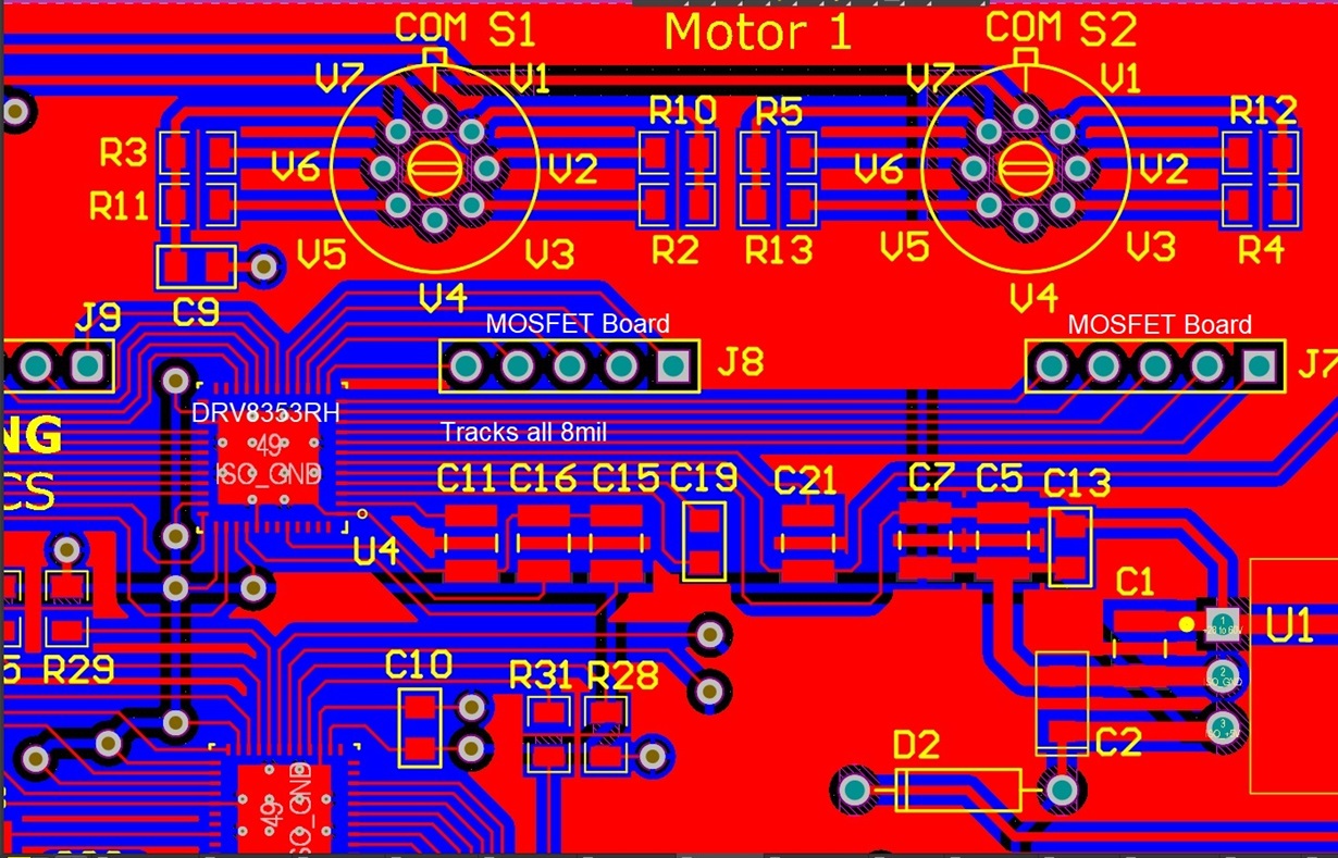
    Gate and SHx node trace widths? - 8mil PCB trace widths

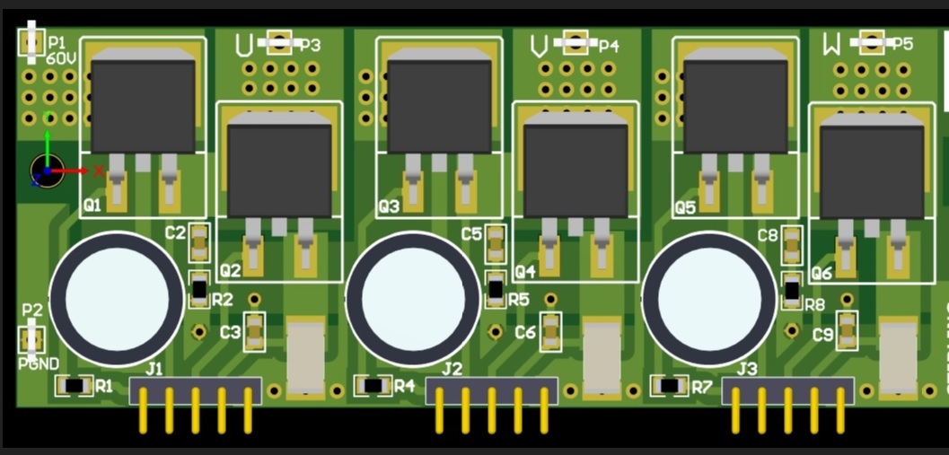
    Distance from driver IC to motor? Including board trace and wire length to motor.- See attached jpeg the distance is about 2" from gate driver to Mosfet gate through the pin headers. The motor is 12" from the Mosfet's via flying leads.


  • Minesh,

    Using the CSD19506KTT, Qgd is only 20nC, to achieve 100nS rise/fall time only 20mA is needed so I would use a low setting for IDRIVE, 450mA is too much.

    8 mil trace widths for SHx and GHx/GLx are quite small. We recommend 20 mils and at least 1oz copper for best results.

    It is also not recommended to have the FETs and DRV on separate boards. The inductance and impedance added by the vias, connectors, cables, and distance can cause big issues for the DRV.

    Have you checked using a scope at the DRV pins for GHx, GLx, and SHx? I imagine you will find ringing there.

    I see that you have some gate resistors, please replace these with 0 ohm since the smart gate drive will manage the current and they can interfere with the smart gate drive feature.

    Please note that the IDRIVE and VDS are sensed at power up and so the rotary switch change must happen before powerup.

    If the FAULT is persistent and you do not have any supplies that are undervoltage, then it is possible that you may have damaged the DRV. This can happen when there is too much transient on the output or gate lines, often caused by IDRIVE being too high.

    Regards,

    -Adam
  • This document discusses board design and layout which we recommend: www.ti.com/.../slva959a.pdf
  • Hi Adam

    Thank you for the detailed reply we will do some detailed investigation and take some scope measurements and get back to the forum of our findings.

    Thanks

    Minesh