This thread has been locked.

If you have a related question, please click the "Ask a related question" button in the top right corner. The newly created question will be automatically linked to this question.

DRV8432: ~ FAULT pin in cycle-by-cycle (CBC) current limiting mode

Part Number: DRV8432

Quote from datasheet:

“The DRV84x2 contains advanced protection circuitry carefully designed to facilitate system integration and ease of use, as well as to safeguard the device from permanent failure due to a wide range of fault conditions such as short circuits, overcurrent, overtemperature, and undervoltage. The DRV84x2 responds to a fault by immediately setting the half bridge outputs in a high-impedance (Hi-Z) state and asserting the FAULT pin low. In situations other than overcurrent or overtemperature, the device automatically recovers when the fault condition has been removed or the gate supply voltage has increased.”

When I send input PWM and short the load with 0.1Ω I can see that the current limiting works. When the 0.1Ω is connected parallel to the load for short time, the ~FAULT pin remains high. When 0.1Ω is connected parallel to the load for longer time, say 0.1-0.5sec ~FAULT pin changes state to low, but DRV8432 remains fully operational - when I remove 0.1Ω undistorted signal appears on the output. However ~FAULT pin remains low until reset. What is the logic behind ~ FAULT pin operation in CBC current limiting mode? Thank you

  • Hi Dimitri,

    Thank you for posting to the motor drivers forum.

    What mode is the driver set to. What are the values of M1, M2, and M3? I just want to verify that the device is indeed in CBC mode. I'm puzzled as to why nFAULT pin drops low and the device continues to operate. CBC current limit protection will not report on nFAULT. One way that nFAULT is pulled low and the device continues to operate is during an undervoltage fault but self recovers once the input voltage is within operating range. Is the GVDD voltage above 8.5V during this case?

    To truly understand what is happening, it would be good to see an oscilloscope image showing the output current, nFAULT, GVDD, and output voltage. Take three measurements. The first one when the current limit is functioning properly. The second one when 0.1Ω is connected in parallel to the load and nFAULT remains high. The third one when the nFAULT drops low and device remains operational. Can you provide these scope images?

  • Hi Pablo,

    Driver is set to dual full bridge mode with CBC M1=M2=M3=0

    PVDD=48V PWM frequency ~400kHz. Each output has LC low pass filter, L=22uH, C=0.47uF.

    Roc_adj=24k ~OTW pin is high all the time, GVDD is +12V all the time

    Screenshots are in attached file.

    Thank you

    to Pablo Armet Nov 17.pdf

  • Hi Dimitri,

    Thank you for providing the information.

    The driver seems to be set up to the appropriate mode. The PVDD value is close to our recommended value of 52V but this shouldn't cause any issues with the driver operation.  

    Given that the OTW is high all the time and GVDD is above 12V, the only explanation for the nFAULT signal dropping low is an overcurrent shut-down as shown in table 1 on the datasheet. An overcurent shutdown fault will place the H-bridge FETs in High-Z state disabling the outputs until the device is reset. The motor should stop rotating and the output current should drop low when this occurs. Are you observing this in your experiments.

    Looking at the waveforms, I am a bit confused on the output waveforms. Figure 1, 2, 3 waveform show the FAULT pin low but you mention in the description that it is high. It is hard to see the values on the images so correct me if I am wrong. Assuming that the FAULT signal is HIGH, the output voltage waveform on Figure 1 is sinusoidal with a minimum negative value which doesn't make much sense to me. Can you send me a screenshot of how you have the load connected to the driver? 

     I also see no major difference in the waveforms between Figure 2 and Figure 4. The amount of time the output voltage is toggling is about the same in both waveforms. Are these two waveforms any different?

    When you had the 0.1Ω load connected for longer time and the nFAULT signal drops low, did the motor continue to rotate or did the current draw stay the same after the nFAULT signal becomes low? Can you verify this for me?

  • Hi Pablo,

    Thank you and please accept my apologies for confusion, I added legends to the screenshots, see attachment.

    >Figure 1, 2, 3 waveform show the FAULT pin low but you mention in the description that it is high. --- Yes, ~FAULT is high

    >the output voltage waveform on Figure 1 is sinusoidal with a minimum negative value --- please see legend, the output swings from +4V to +44V

    >I also see no major difference in the waveforms between Figure 2 and Figure 4. The amount of time the output voltage is toggling is about the same in both waveforms. Are these two waveforms any different? --- Yes, they are different: in Figure 2 ~FAULT is high and in Figure 4 ~FAULT is low

    >When you had the 0.1Ω load connected for longer time and the nFAULT signal drops low, did the motor continue to rotate or did the current draw stay the same after the nFAULT signal becomes low? Can you verify this for me? --- I don't use the motor, I use resistive 4 Ohm load. After the ~FAULT signal becomes low, and short is removed  the DRV8432 returns to normal operation (see Figure 5). I expect that ~FAULT self clears once short is removed but ~FAULT remains low until reset.

    Thank you again,

    Dimitri

    to Pablo Armet Nov 19.pdf

  • Hi Dimitri,

    Thank you for clarifying and adding the descriptions on the scope images. The waveforms makes more sense to me now.

    What is the PWM frequency and duty cycle of the input signals (PWM_X)? Or are these signals constant (set HIGH or LOW)?

    Since the CBC is dependent on the input signals toggling from high to low, the CBC will behave differently when the input signals (PWM_X) are constant as explain in the datasheet: "It is important to note that if the input to a half bridge is held to a constant value when an over current event occurs in CBC, then the associated half bridge will be in a HI-Z state upon the over current event ending. Cycling IN_X will allow OUT_X to resume normal operation"

    If you are keeping the input signals constant, I am wondering if this can potentially explain the issue you are observing.

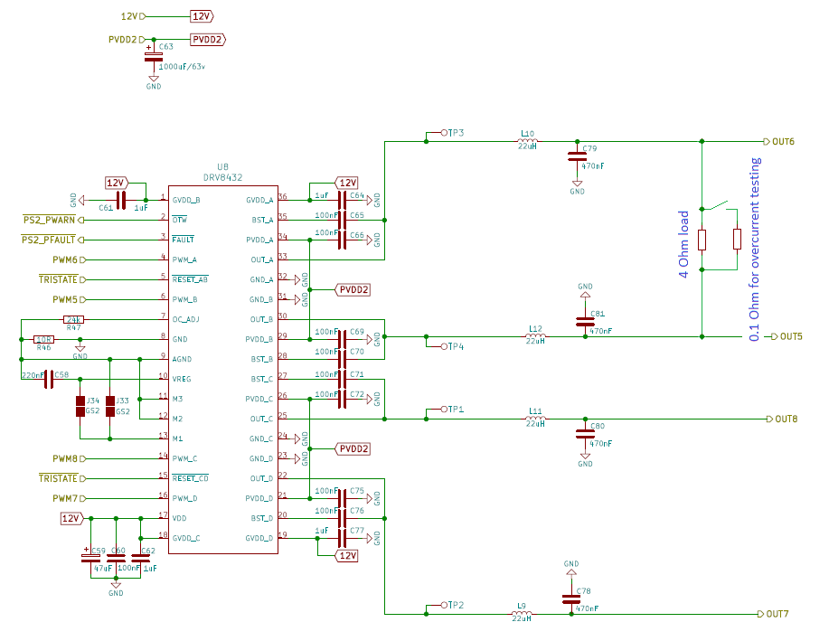
    Also, so I can better understand your set-up, can you send me a diagram of how the load is connected to the driver and where exactly the load, LC filter, and 0.1ohm resistors are located.

    I will wait for you to provide the information requested. In the meantime, I will continue to do more research.

  • Hi Pablo,

    >What is the PWM frequency and duty cycle of the input signals (PWM_X)? --> It is 400-500kHz PWM

    There is no difference in schematic from SLOU291AA DRV8432EVM Motor Drive Evaluation Board

  • Hi Dimitri,

    Thank you for providing the schematic. 

    Let me take some time to take a look at the schematic and I will reply by 11/25 or earlier. 

    By the way, you mention that the frequency is 400kHz to 500kHz but what is the typical duty cycle?

  • Hi Dimitri,

    I apologize I don't have a response for you today. I am still working at understanding what could be causing the issue you are observing. 

    Due to Thanksgiving holiday here in the US, expect a reply from me by 11/30.

    Thanks for your patience and understanding.

  • Hi Pablo,

    To answer your question the typical duty cycle varies from 1 to 99%.

    Best regards,

    Dimitri

  • Hi Dimitri,

    I apologize in advance for the multiple question but I really want to understand your set-up in detail so I can determine if this problem is cause by your set-up or if it is caused by abnormal behavior of the device. Since your design is similar to our EVM, it might be possible for me to try and recreate the abnormal behavior using the DRV8432EVM. 

    1. what is the specific frequency and duty cycle for PWM_A, PWM_B, PWM_C, and PWM_D. You mention that the frequency varies from 400kHz to 500kHz and the  duty cycle from 1% to 99%. I want to confirm, are you saying that the duty cycle and frequency is not constant?

  • Hi Pablo,

    The PWM frequency is constant, it is different between boards (depending of firmware)

    Duty cycle varies when DRV8432 generates sine wave on the output after filter, otherwise it is 50%.

    My observations:

    a) in CBC mode short circuit between outputs causes ~FAULT low

    b) when short is removed ~FAULT stays low unit reset. I expect that ~FAULT self clears once short is removed.

    Is my assumption wrong?

    Thank you again,

    Diimitri

  • Hi Dimitri,

    Thanks for the clarification.

    You're observations are not entirely correct. Let me clarify some points:

    1. CBC mode has two protection levels. In level 1, the current is limited without nFAULT latching LOW and disabling the outputs. This CBC current limiting function is useful for limiting inrush current during motor start up. Level 2 occurs when the current rises well above the current limit (set by OC_ADJ) which causes the outputs to be disabled and nFAULT latching low. Level 2 can be view as OC latching (Overcurrent protection). Level 2 is caused mainly during a short to GND or power or a short between the outputs like in your case. When the level 2 protection is triggered, the only way to unlatch the fault and resume operation is to cycle power or reset the device. However, you mention that the outputs resumed normal operations despite nFAULT being LOW. Is this correct? The device is not supposed to behave this way so we'll have to take a closer look to understand what's causing the outputs to re-enable if this is the case.
    2. As mentioned in (1), during level 1, current is being limited without causing nFAULT to become LOW. However, if the current rises dramatically to a point where the current limit circuitry cannot properly limit the current, a level 2 protection is trigger where the outputs are disabled and nFAULT is LOW. I believe this is what is happening in your case. when you keep the short for short amount of time, the current has not risen to the point where a level 2 protection is triggered. However, after some time, the current does rise high enough to trigger a level 2 OC fault. Can you try causing the short with a 0.5-1Ω resistor and observe if the outputs are disabled? If the CBC level 2 fault takes longer to trigger or does not trigger at all, then this will prove my statement above.