This thread has been locked.

If you have a related question, please click the "Ask a related question" button in the top right corner. The newly created question will be automatically linked to this question.

LM5060-Q1: Diodes specs required for Reverse Polarity protection with Diodes

Part Number: LM5060-Q1
Other Parts Discussed in Thread: LM76202-Q1, LM74800-Q1, TIDA-01167

Hi,

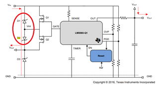
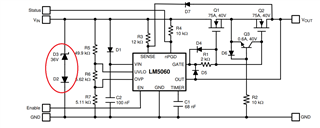
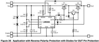
We are going to use LM5060Q1MMX/NOPB for reverse polarity protection with the diodes options as shown in the snapshot given below. I am going through the datasheet but there is no specs defined for the diodes except the Zener diode that can be selected based on the application. 

Datasheet does defines that what are these diodes used for but there is no explanation about how much the rating they should have or like how much the forward current one should supports. Is there any other document that is defining this circuit in more detail?

Kind regards,

Muhammad Awais

Thanks,

Mat

  • Hi Muhammad,

    Thanks for reaching out!

    What is the current rating of the system? Please refer https://www.ti.com/tool/TIDA-01167 design for more details. Voltage rating of these diodes is more important than these path don't carry high current, 100mA to 200mA current capable diodes are good enough.

    Have you looked at new devices LM76202-Q1 or LM74800-Q1 ?.

    Best Regards, 

    Rakesh

  • Hi Rakesh,

    Thanks for your kind reply and also for sharing the link. Our voltage range is between 8 to 18V.

    We will also look into the new devices but I am afraid that option like LM76202-Q1 (looks great) don't have high current capacity (max 2.23A). 

    Kind regards,

    Muhammad Awais

  • Hi Rakesh,

    I am following the document link that you have referred and I would like to clarify the following;

    1. There is not input transient protection added on VIN as shown in the snapshot given below to allow the path for current when Q1 and Q2 goes off during Over-Current shutdown;

    Whereas, as per the datasheet the have showed the TVS along with a diode as states it as transorb circuit to avoid stressing input capacitors with reverse polarity as shown below. Please suggest about it as we do need to protect our input from Transients, secondly there is no more explanation or addition of it on TIDA-01167 reference design link. I would also like to know about the ratings for the diode, and I am assuming that D2 is only to protect the TVS diode in case of battery reverse polarity!

    2. Please confirm that if we have to use TVS diodes for Over-current shutdown and input transient protection then do we have to add both of these above mentioned setups of diodes?

    Kind regards,

    Muhammad Awais

  • Hi Muhammad,

    The configuration in the datasheet is only for input reverse polarity protection, where you can select TVS diode D3 just above the max operating voltage (18V in your case)

    TIDA-01167 proposes the TVS configuration to handle  ISO 7637-2, ISO 16750-2 transient pulses. D1 and D3 forms the TVS diode at the input. The configuration helps to transfer the transient input energy to the load. The selection of these diodes depends on whether your system needs to handle suppressed load dump or unsuppressed load dump. Let me know.

    TIDA-01167 used 5kW diodes to handle suppressed load dump events.

    Best Regards, 

    Rakesh

  • Hi Rakesh,

    Yes we do have a chance of Load Dump if somebody will disconnect the battery while the engine is running. I am assuming that it will unsuppressed load dump, if so then please confirm if TIDA-01167 strategy is meant to be for?

    Kind regards,

    Muhammad Awais

  • Hi Muhammad,

    I suggest to use LM74800-Q1 as per Figure 10 in https://www.ti.com/lit/an/slvaes2/slvaes2.pdf straight forward solution than TIDA-01167

    Best Regards, 

    Rakesh

  • Hi Rakesh,

    Actually client wants to stick to this chip. 

  • Hi Rakesh,

    Here is the finalized schematic. Please let me know if there is anything missing;

    By the way as per TIDA-01167 there are two in series 0.1uF caps at the input. Any reason for doing so?

    Kind regards,

    Muhammad Awais

  • Hi Muhammad,

    Schematic looks fine to me.

    To support ISO transients, high voltage caps are needed which are costly. So, two series caps are used to increase the effective voltage rating of the input cap system.

    Best Regards, 

    Rakesh

  • Hi Rakesh,

    Got it, Thanks for the checking the schematic as well. 

    Kind regards,

    Muhammad Awais