Other Parts Discussed in Thread: LM5155
Hello,
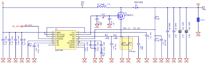
I power on for first time new DC/DC step-up from 24V to 100V.
At the moment load is 50kohm resistor, it will be an RC load, approssimately 200kohm in parallel with 100nF.
It seems working, I have 100V on output.
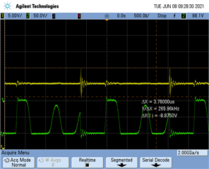
I found this signal after inductor, is it correct? why there is a secondary and third wave?
To improve efficiency and avoid EMC/EMI problems, I have to change inductor value and switching frequency?
Thank you a lot
Ch1 Vgate, Ch2 Vinductor
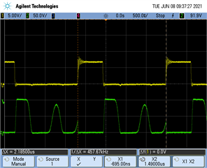
Ch1 Output (100Vdc), Ch2 Vinductor