This thread has been locked.

If you have a related question, please click the "Ask a related question" button in the top right corner. The newly created question will be automatically linked to this question.

BQ24295: D+ D- pins, supplement mode, inductor questions

Part Number: BQ24295

Hello,

We are looking to build a system with BQ24295 and here are some design questions:

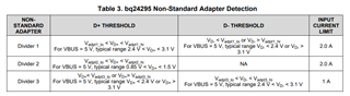
- The Vin is from a DC-DC converter at 4.4V and we want the input current limit to be 3A. From the datasheet it isn't clear what to do with D+/D- pins when not providing power from a USB connector. In this specific case how to create a detection of charging port with 3A input current limit so that this value is written to REG0[2:0] on powering on input side?

- Once REG0[2:0] is set to 3A limit, the actual limit is set as per ILIM pin's resistor, right?

-The battery would need slow charging to prolong its life, so max charging current needs to be 300 mA. This means with 20% as max ripple current of inductor, its 60 mA. Using this value if we calculate the inductance needed, its more than the 2.2uH recommended. So how do we go about this?

-There is no load on PMID as there is no requirement of OTG. As I understand from another thread in this case the min capacitance needed at PMID is 8.2 uF. Please confirm this.

- If there is no need for temperature sensor at TS pin, how can this pin be setup for no error?

Thanks, Prithvi

  • Hello Prithvi,

    The D+/D- detection will always be done, but you can overwrite the value with your MCU after detection. Or you can use the non-standard which can be up to 2A.

    The actual limit is whichever one is lower, either the register ILIM or hardware pin setting.

    The recommended value is for stability, why is the max inductor current for your system 20% of ICHG?

    Yes you still need 8.2uF on the PMID pin even without OTG.

    For the TS question there are other threads for that question here: e2e.ti.com/.../bq24295-bq24295-standalone-and-not-use-ts-pin

    Sincerely,

    Wyatt Keller

  • Thanks Wyatt for the quick reply. Few follow up questions

    1. As I understand if we want 2A non-standard detection, one option is to get a voltage of 0.85V < VD+ < 1.5 V and connect D- to GND?

    2. Actual limit is understood.

    3. This higher inductance calculation is coming from the Inductor selection section 9.2.2.1 in the datasheet where it is mentioned the inductor ripple current can be 20 to 40% of max charging current (300 mA in our case). So if we use this in L = Vin x D x (1-D)/(fs * Iripple), since I ripple is 20% of 300 mA, the L value would be more.

    4. Thanks for confirmation on 8.2 uF

    5. Understood. We'll get 60% of REGN value at TS pin.

    Regards, Prithvi 

  • One more question

    6. In the datasheet it says to connect PGND and AGND at one point. What does AGND refer in this case? In the eval board there are two GND planes, one in top 3/4th of board and other in bottom 1/4th.

    Thanks.

  • Hello Prithvi,

    Yes that's one way to get 2A ILIM:

    Power ground and analog ground can be tied together and it is shown the datasheet to do this, PGND is used for higher current paths, just make sure there's no voltage differences between PGND and AGND (absolute max is +/-300mV).

    Sincerely,

    Wyatt Keller