


Hi expert,
Customer did TPS54225 short circuit test by push "short" on e-load and it's always SHORT. The ENABLE is controlled by CPLD. Once Vo drop, CPLD will disable ENABLE and then ENABLE again.
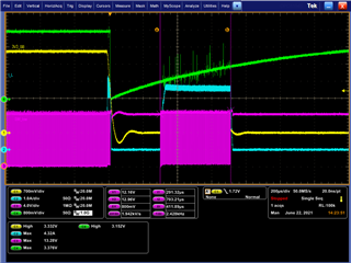
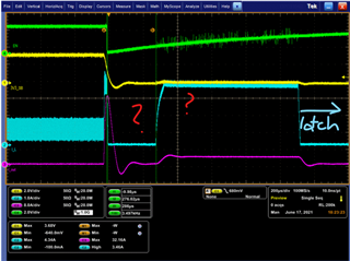
One thing from below waveform we can't understand is after short circuit, trip UVP and it lasts about 286uS then converter start switching again(seems in OCP status) even ENABLE is not yet > 2Vh.
After ~800uS, ENABLE > 2V, it stop switching and latched. It can be only recovery by toggling ENABLE.
Our questions are
1. why tps54225 would operate even ENABLE < 2V?
2. UVP should be latch protection after UV 250us. Why it's not latched?
Ch1: 3.3Vo
Ch2: Iinductor
Ch3:Vsw
Ch4: EN
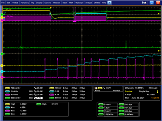
Ch1: 3.3Vo
Ch2: Iinductor
Ch3:Iout
Ch4: EN
Regards,
Allan
