This thread has been locked.

If you have a related question, please click the "Ask a related question" button in the top right corner. The newly created question will be automatically linked to this question.

TPS62740: How to eliminate the saw tooth by using filters ?

Part Number: TPS62740

hey TI team,

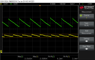
we are using TSP62740 IC in our device. we are getting saw tooth waveform at the output of the IC (Green waveform).

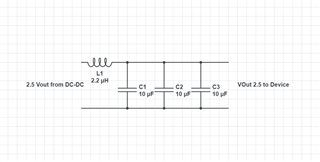
we tried to reduce it by using passive LC filter(2.2uH,10uF). 

can you people help us out how can we further reduce and make almost straight line.

I request you to assist us

  • Hi Vinayak, 

    Thanks for your question.

    What are the operating conditions during your evaluation (VIN, VOUT, IOUT)?

    It seems to me that the green waveform could represent the behavior of the converter in Power Save Mode (please refer to section 9.3.1 of the datasheet for details). Since the converter reduces it's switching frequency at light load, it is expected to obtain an higher ripple.

    One solution could be to select a forced PWM device, for example TPS62824ATLV62568A  or TPS628510. These devices do not have a PSM, therefore you would keep the ripple reduced across load conditions.

    If you want to keep using TPS62740, you have mainly two options:

    • Add a dummy load to ensure PWM operation even at light load (this would give you an additional power consumption).
    • Filter VOUT; this can be done either with a low pass filter or inserting an LDO (preferred solution) after the converter.

    Please ask again if you need further support.

    Thanks,

    Stefano

    All information in this correspondence and in any related correspondence is provided “as is” and “with all faults”, and is subject to TI’s Important Notice (http://www.ti.com/corp/docs/legal/important-notice.shtml).

  • Hi Stefan,

    Thanks for your reply

    here are operating conditions (VIN=3.6V,VOUT=2.5,IOUT=50mA)

    as suggested by you we checked with 3 different loads(47e,50e,1.2k), the output obtained was still not smooth, ripples are still present.

    The sawtooth is no longer visible though.

    Rippled output is not suitable for our application.

    any other suggestions

    Thanks,

    Vinayak

  • Hi Vinayak, 

    Thanks for the update.

    I just want to clarify that some ripple is normal for our devices, since they are switching regulators.

    If you want to suppress it, a possible solution is to put an LDO after the Buck converter.

    Please ask again if you need further support.

    Thanks,

    Stefano

    All information in this correspondence and in any related correspondence is provided “as is” and “with all faults”, and is subject to TI’s Important Notice (http://www.ti.com/corp/docs/legal/important-notice.shtml).

  • Hi Stefano,

    our device is power constrained so we are not going for LDO due to it's power consumption. Ours battery operated device.

    so we are using Passive LC(3x2.2uH,1x10uF) filter at the the end of the output. 

    after applying 3 stage filter the saw tooth reduced to from 8mV to 2.8mV Pk-Pk. can we reduce more ?

    any other solution ?

    Thanks in advance.

  • Hi Vinayak, 

    Got it.

    As already said, the output ripple is intrinsic of any switching regulators.

    I believe that 8/2.8mV is already a very good results for standard applications.

    The only thing you could do is to further filter the output.

    This can be done using either a passive filter as you are currently doing (please pay attention that the switching frequency in Power save mode is proportional to the output load, therefore your filter should adapt to multiple frequencies), or using an LDO in series to the buck converter.

    For this second solution you can reduce the power dissipation decreasing the voltage from 3.6V to 2.8/2.7V (you need to consider VOUT ripple and the drop on LDO) and then use the LDO for final conversion to 2.5V.

    Thanks,

    Stefano

    All information in this correspondence and in any related correspondence is provided “as is” and “with all faults”, and is subject to TI’s Important Notice (http://www.ti.com/corp/docs/legal/important-notice.shtml).

  • Hi Stefano,

    We implemented filters in our device but unfortunately we didn't get expected results. I have shared the Image please correct if we missed something..

    how can we improvise our circuitry ? assist us on it.

    how can we achieve good results. 


    Thanks in advance.

  • Hi Vinayak, 

    I don't believe you would be able to cover a wide frequency span using a simple LC filter.

    I would again advise you to use an to LDO. This should be the best solution to minimize the ripple across switching frequency variations.

    Thanks,

    Stefano

    All information in this correspondence and in any related correspondence is provided “as is” and “with all faults”, and is subject to TI’s Important Notice (http://www.ti.com/corp/docs/legal/important-notice.shtml).

  • Hi Stefan,

    Can you suggest some LDO's for same IC. 

    Thanks,

    Vinayak

  • Hi Vinayak, 

    Thanks for your question.

    I am personally not an expert of LDOs (we support Buck converters).

    Feel free to consult our webpage: Linear regulators (LDOs) | Overview | Power management | TI.com to select the ones most suitable for you specific application.

    Thanks,

    Stefano

    All information in this correspondence and in any related correspondence is provided “as is” and “with all faults”, and is subject to TI’s Important Notice (http://www.ti.com/corp/docs/legal/important-notice.shtml).

  • Hi Stefan,

    My concern is to eliminate the ripples from the output will LDO do it ? 

    Thanks,

    Vinayak

  • Hi Vinayak, 

    As said before the output ripple is a characteristics of our converter, therefore you cannot eliminate it at priori but you need a specifications on how much ripple you can accept.

    Said so, an LDO is a linear regulator, without switching, therefore it should help you to suppress the ripple as much as possible within is bandwidth. 

    Therefore I would advise you to first establish the specifications on the output voltage you want to get and then test the LDO you have selected in the real application, to see if it can meet your requirements.

    For standard applications, the LDO's ripple is usually negligible.

    Thanks,

    Stefano

    All information in this correspondence and in any related correspondence is provided “as is” and “with all faults”, and is subject to TI’s Important Notice (http://www.ti.com/corp/docs/legal/important-notice.shtml).

  • Yes, I have gone through the TI's website and found some suitable LDO's for our device. I requested samples for it.

    Thank you,

    Vinayak

  • Hi Vinayak, 

    Very good.

    Let me know the results of your measurements.

    Thanks,

    Stefano

    All information in this correspondence and in any related correspondence is provided “as is” and “with all faults”, and is subject to TI’s Important Notice (http://www.ti.com/corp/docs/legal/important-notice.shtml).