This thread has been locked.

If you have a related question, please click the "Ask a related question" button in the top right corner. The newly created question will be automatically linked to this question.

TPS24720: IMON and design calculator

Part Number: TPS24720

Hello,

I had a couple of questions regarding the TPS24720.

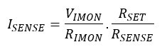
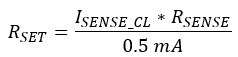
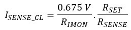
How does one find the relationship between the current through the sense resistor and the voltage at the IMON pin? The datasheet simply says that they are proportional but what is the constant of proportionality? Will the voltage at this pin be affected by the current limit I set? A graph or an equation for calculating the IMON voltage would be helpful.

And in the design calculator the input cells for the capacitance values specify that it should be given in nF. However when looking at the design summary the same numbers are taken but given in uF without any factor of 1000 conversion. What is the correct unit for these capacitances?

Martin

  • Hi Martin,

    Welcome to E2E !!! Thanks for your interest on TI Hot Swap controllers. I will get back to you by end of the day today. 

  • Hi Martin,

    Please see the responses below in the order of your queries.

    1)  Relationship between the current flowing through the sense resistor and the voltage at the IMON pin can be described as follows.

    For best performance, a current of approximately 0.5 mA (referring to the RECOMMENDED OPERATING CONDITIONS table) should flow into the SET pin and out of the IMON pin when the TPS24720 is in current limit. The voltage across RSET nominally equals the voltage across RSENSE. Therefor, RSET can be calculated as follows.

    ISENSE_CL is the current flowing through the RSENSE when device is in current limit. Now, RIMON should be calculated in such a way that the voltage across IMON pin is 0.675 V (typical) when the device is in current limit. Current limit will kicks in only when the voltage at IMON pin reaches to 0.675 V (typical). 

    2) Selected Timer capacitance (CT) should be in nF. Sorry for the mistake in "Design Summary" section. We will modify in the next revision of the design calculator. 

    Please let us know if there is any more query. 

  • Hello, I just had a quick follow up question regarding this part and I didn't want to start another thread.

    I see in the typical application schematic the TPS24720 is shown with a 470uF capacitor as Cout. Am I correct in assuming that this large capacitance is just the sort of typical load capacitance you'd see across all the components receiving power from this device, and that a large bulk capacitor of hundreds of uFs is not required at the output? 

  • Hi Martin,

    You're correct. It's recommended that he OUT pin should be bypassed to GND with a low-impedance ceramic capacitor in the range of 10 nF to 1 µF.