- Ask a related questionWhat is a related question?A related question is a question created from another question. When the related question is created, it will be automatically linked to the original question.
Original question:

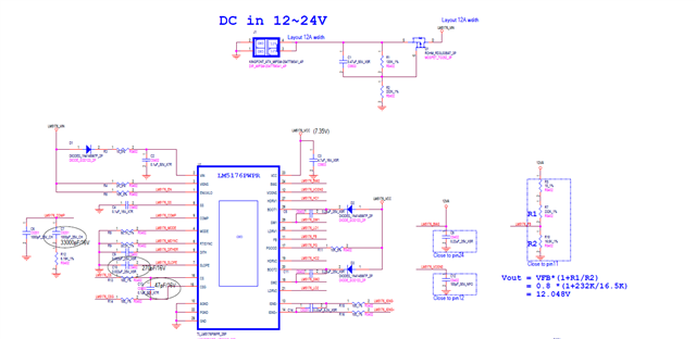
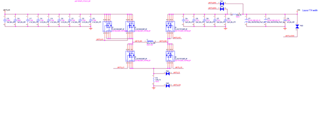
[FAQ] LM5176: Difference between the standard and -Q1 versions