This thread has been locked.

If you have a related question, please click the "Ask a related question" button in the top right corner. The newly created question will be automatically linked to this question.

LM3421: Can't reach the wanted current

Part Number: LM3421
Other Parts Discussed in Thread: TIDA-050002

Hi all,

I try to reach a target of 3.6 Amps to supply a high power COB LED (LED voltage up to 38V) but I stay under 3 Amps. Do you have any idea?

Circuit

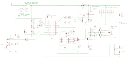
As the input voltage is from 16V to 48V I use the buck-boost topology and the switching frequency is set to 1MHz to minimize the system size.

I don't think the regulation loop is faulty because the signal on the voltage across R_SNS stay under 1.24V threshold and the COMP pin is around 6V. I suspect the cause is in the main switching loop, maybe it is a basics of the buck-boost topology but I don't achieve to pinpoint it.

I tried the following changes:

  • R_OV1_0 value: changed to 10k to inhibit the over voltage protection.
  • R_LIM value: with R_LIM=0.033R I reach 2.2 Amps, with R_LIM=0.025R 2.8 Amps but the power dissipated power increases too much.

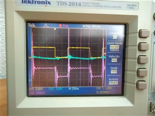
Here the signal on Q1 gate (yellow), the current in R_SNS (blue) and the signal on IS (pink) with R_OV1_0=10k and R_LIM=0.025R

Scope Q1_gate, I_R_SNS, IS

Thanks.

Guillaume.

  • Guillaume,

    Since this is high power and really high frequency...Can you send me a layout of the design also.  

    Thanks Tuan

  • Hi Tuan,

    You can download the layout at https://we.tl/t-9YEEAaKz3Z.

    Thanks

    Guillaume.

  • Hello Guillaume,

    Thank you for the response. Tuan is out this week, but he will get back to you on this layout when he gets back next week.

    Thanks,

    Caroline

  • Hi Guillaume,

    What input voltage are you testing this at?

    You have an input voltage range of 16V to 48V with an output of up to 38V at 3.6A.  As a buck-boost the MOSFET current at 16V will be over 12A when the MOSFET is on (not including efficiency).  Have you gone through the design calculations for this design?  Rilim will need to be much lower.  Also, at this power level and switching frequency there will be quite a bit of power loss that has to be properly dealt with using adequate heatsinking and part selection.  The inductor may have loss issues as well due to core loss and high currents.

    Best Regards,

  • Hello Caroline,

    Thank you for your response, I will wait for Tuan to return.

    Thanks,

    Guillaume.

  • Hi Irwin,

    The nominal voltage and the one I use for tests is 24V. For voltages under this value, there will be firmware limitations so please consider 24V as input voltage.

    To calculate the components values, I use the "9.2.1 Basic Topology Schematics" recomendations from the last LM3421 datasheet (rev. G). From this, I made this excel workbook for the calculation: https://we.tl/t-u5z8Qwd94S.

    I re-calculate from scrach the current in R_LIM (without the datasheet formulas) and found the same value of around 8A. Probably this is a big mistake or misunderstood, so big that I can't see it. Maybe I use a too high inductor and so obtain a too low delta_I_L to be properly detected (delta_I_L = 440mA compared the R_LIM average current durin T_on).

    The heatsinking Is not a problem for me as the global system is watercooled. The Coilcraft simulator give me the inductor value = 25µh and the losses acceptable for 10A.


    Thank you for your help.

  • Hi again Irwin,

    You wrote "the MOSFET current at 16V will be over 12A". That troubles me. Following the datasheet recommendations for the buck-boost topology (9.2.1 Basic Topology Schematics), with Vin=16V, I get D_max=0.704. So It_max in Q1 will be D_max/(1-D_max)*Iled=8.6A. 

    How do you calculate 12A ?

    Thanks.

  • Hi Guillaume,

    I(T) isn't the peak current, it's a calculation for transistor current.  A buck-boost is discontinuous.  When the MOSFET is on the inductor current charges from the input voltage, nothing goes to the load.  When the MOSFET is off the inductor current goes to the load.  Ignoring current ripple and efficiency, using 3.6A load current and 0.703 duty cycle the current flowing to the load is 3.6A/(1-0.7037) = 12.15A.  If you use the I(T) equation using dutymax less than 0.5, for example 0.4, I(T) = 0.4/(1-0.4)*3.6A = 2.4A, the MOSFET current cannot be less than the output current.

    I back calculated your two sense resistors:

    33 mohm, using 0.245V = 7.42A.  If your output is 2.2A, 2.2A/(1-0.613) = 5.9A

    25 mohm, using 0.245V = 9.8A.  If your output is 2.8A, 2.8A/(1-0.613) = 7.2A

    The above calculations do not include efficiency, current ripple (0.43 Apkpk) or supply voltage drop.

    In the scope picture is appears Vis is approximately 0.24V and the duty cycle is close to 15/(8+15) = 0.652.  It also looks like the switching frequency is approximately 870 KHz.  This is high for this power level.  It also appears your losses are going up significantly going from 33 mohm to 25 mohm, 33 mohm: (5.9A+0.43A/2)/7.42A = 0.824 or 82.4% and 25 mohm: (7.2A + 0.43A/2)/9.8A = 0.757 or 75.7% though there can be other reasons for this.

    https://www.ti.com/lit/pdf/snva376?keyMatch=LM3421 The current sense resistor in this design is 0.06 ohms for a much lower power level.

    You can look at TIDA-050002 equation 6 and 7 on page 8 for a higher power level design, just note that the Vis is lower on this part:  https://www.ti.com/tool/TIDA-050002?keyMatch=TPS92692

    I would look at lowering the switching frequency if that is possible.

    I included my calculations below:

    Vinl 16 V  
    Vinnom 24 V  
    Vinh 48 V  
    Vled 38 V  
    Iled 3.6 A  
    dutyl 0.703703704    
    dutynom 0.612903226    
    dutyh 0.441860465    
    Ioutswl 12.15 A  
    Ioutswnom 9.3 A  
    Ioutswh 6.45 A  
           
    Lind 0.000033 H  
    Rilim 0.033 ohm  
    Viliml 0.215 V  
    Rhsp 1082 ohm  
    Rcsh 12400 ohm  
    Vsns 0.1082 V  
    Icsh 3.606666667 A  
    Vilimnom 0.245 V  
    Rct 24000    
    Crct 0.000000001 F  
    Rsns 0.03 ohm  
    eff 0.85    
    Ilim 7.424242424 A Not including eff (0.245V)
    Iliml 6.515151515 A Not including eff (0.215V)
    Fsw 1041666.667 Hz  
    ton 5.88387E-07 sec  
    toff 3.71613E-07 sec  
    diLon 0.427917889 Apkpk  
    diLoff 0.427917889 Apkpk  
    Ipk 3.820625611 Apk  
           
    Iloadave 12.15 A average inductor current at 16V

    Best Regards,

  • Hi Irwin,

    Thank you so much! You pointed me the source of the problem. I have to reduce R_LIM to around 20 mR, I was just missing the right formula. With a 22 mR I had left and the appropriate dissipator I reach 3.2A.

    Thank you again.

    Best regards.

    Note: Sorry for the delay in response