This thread has been locked.

If you have a related question, please click the "Ask a related question" button in the top right corner. The newly created question will be automatically linked to this question.

UCC28180: How does this circuit work in the 280Vac to 24Vdc 30W buck reference design

Part Number: UCC28180
Other Parts Discussed in Thread: TIDA-00652,

Hi team,

My customer is looking for an in depth explanation of how this particular circuit operates in the attached reference design. Can you explain, or point out where in the reference design it explains the operation of this particular part of the circuit?

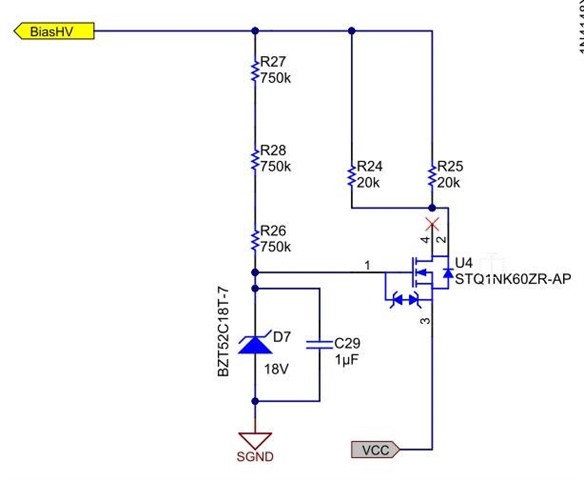
Reference design and full schematic are also attached.

Thank you!

Lauren230Vac to 24Vdc, 30W UCC28180 Buck Schematic.pdf

230Vac to 24Vdc, 30W Buck Ref Design based on UCC28180.pdf

  • Hello Lauren,

    This portion of the reference design circuit is not discussed in the TIDA-00652 documentation.
    Its sole purpose is to charge up the VCC capacitor on the PFC controller at start-up. 

    In most applications of the UCC28180, there is a separate source of bias voltage for VCC, but in this case, bias is generated from the "MAG" winding of the buck inductor while it is switching.  Since there is no switching before power-up, MOSFET U4 provides a charging current path from the rectified high-voltage node when AC power is applied.  Zener diode D7 establishes an 18-V gate voltage, so the source voltage will be a few volts lower, say15~16V up to which VCC can charge.

    R26,27,28 provide bias current to the Zener diode, and R24,25 limit the charging current.
    Since this circuit is always on when power is applied, I suggest to increase the values of R24 and R25 to obtain the minimum current necessary to charge up the VCC caps within the required start-up time interval at the lowest input line voltage.  This will minimize bias power loss after start-up.

    Regards,
    Ulrich