A related question is a question created from another question. When the related question is created, it will be automatically linked to the original question.
If you have a related question, please click the "Ask a related question" button in the top right corner. The newly created question will be automatically linked to this question.
[FAQ] TPS62130A: How to use the Power Good (PG) pin?
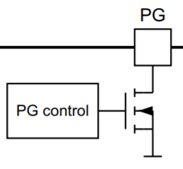
The Power Good (PG) pin, used in many of TI’s TPS62x family of step-down converters, is able to signal if the output voltage is still providing power under normal device operation. The PG pin is an open-drain output which means it is normally a high-impedance output unless a condition is met to drive the pin low when the device has power through Vin. To use the PG pin a pullup resistor to a positive voltage rail is needed. Typically, Vout is used, but any positive voltage less than the rated maximum can be implemented. If the PG pin is not used, it is recommended to be tied to GND or can be left floating. The pullup resistor is chosen to limit the current into the PG pin to a 2 mA maximum for the case of TPS62130(A).
Device Specific Examples
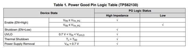
For the TPS62130 the following logic table is followed to determine when PG will follow the pullup voltage level or be brought low to GND.
VTH_PG is the power good threshold voltage that has a hysteresis. The only condition that triggers PG to be LOW is when the output voltage falls below 90% of its steady state value. Once the output voltage rises above 95% then the PG pin will be HIGH because of the high impedance output causing no voltage drop across the pullup resistor. It is important to note that if an external voltage rail is used in this mode, PG will remain high even if the output voltage turns off because of shutdown, UVLO, or thermal shutdown.
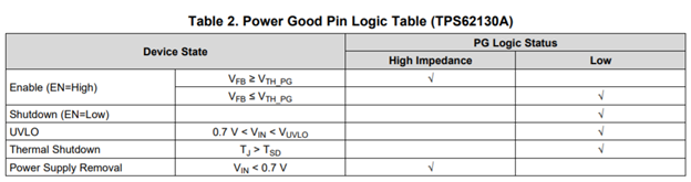
For the TPS62130A the following logic table is used.
The main difference between the PG pins of the TPS62130A and TPS62130 is that the A version can be used to actively discharge Vout through the PG pin under Thermal Shutdown, UVLO, and Low EN conditions. Otherwise, these two parts can be interchanged with Pin-to-Pin compatibility.
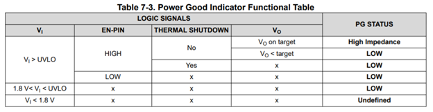
For applications that use the PG pin it is recommended to use the A version as it provides better functionality per the Logic Table. A newer edition of this part which is recommended over the TPS62130(A) is the TPS6290x which implements the LOW PG status as a standard functionality. The TPS6290x follows the following logic table below:
Typically, the datasheet of the part will give guidance about what conditions cause the device to have a LOW or High Impedance PG status.