This thread has been locked.

If you have a related question, please click the "Ask a related question" button in the top right corner. The newly created question will be automatically linked to this question.

LM3410-Q1: LM3410YMF/NOPB

Part Number: LM3410-Q1
Other Parts Discussed in Thread: LM3410,

hi  expert :can you give us some help ?

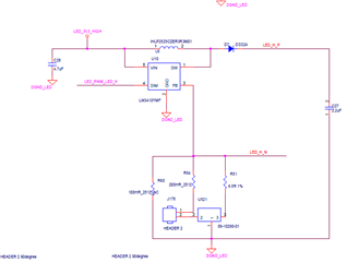
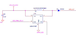
The LM3410YMF /NOPB is used in led driver  , when the led's current is about  100 mA  , The lm34ymf can work well . But when the led's current is about  800 mA ., the  Lm34ymf become bad 

   when led's current is above 300mA .,i find that the Fb pin's voltge of LM3410 is always  100mv    The normal FB's voltage shoulde be  0.2v  >where is the bug ?

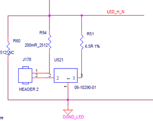
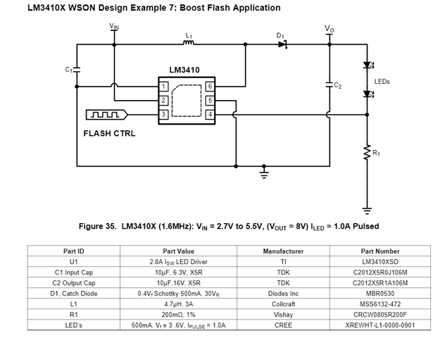
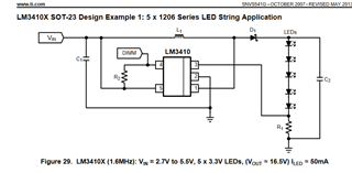
the  fellowing is  our circuit  but the r1 = 400mR  ,  where is the bug  of FB's voltage ?   Whether is the LM3410YMF not suit for the  bigger current ? such as  above 100mA     /Whether is the LM3410X for the high LED current  circuit ?


thank you   

                       lchaoyong

  • Hello,

    Do you have a schematic of your design?

    What is your input voltage and output voltage?

    What is the power source?  Have you monitored the input voltage to make sure it is not falling?

    what does when the LED current is 800 mA the LM3410 becomes bad?  Damaged?

    Best Regards,

  • hi   Irwin:

    Good

    1 Our  sch is   fellowing the reference  typical   LM3410X  circuit(see fellowing  only 50mA  )  ,  I want the led's current is about 800mA or 500mA  So  the  r1 is changed to  240 mR or  400mR for test 

    The c2 is 10uf  , the L1 is about 4.7uh (5A) or 10uh ( 5A) , The chip is LM3410YMF /NOPB(500k) in our circuit  

    (NOTE  The  LM3410X (1.6M)is used in  reference) 

    2 The input voltage is about 5v   max  5A  (source :DC power supply 5v  /10A) 

    Have you monitored the input voltage to make sure it is not falling?//it is good 

    4) what does when the LED current is 800 mA the LM3410 becomes bad?  Damaged?//  change the  R1 to  240mR . I  need  the led's current  about  800 mA   But i find that  when the led's current is above 300mA  , the  Lm34ymf' FB's  voltge of LM3410 is always  100mv  with bigger  noise ,  the led  light become  flicking ,more Overshoot ( The typical normal  fb's voltage  is  about  0.19v ,)   Can the  LM3410YMF /NOPB not support  800 mA led's current  ?

    5) Whether is the LM3410YMF(560k) not suitable  for the  bigger current ? such as  above 100mA     /Whether is the LM3410X (1.6M)only  suitable for our  LED current  circuit  ( 1A)

        thank your !

    lchayong 

  • hi  irwin :1 the fellowing is our sch


    2) I test the chip LM3410X (1.6M) , I want the led's current become 1A ( change the R54  to 200mR )  But The two series led's current is always 100 mA .The Fb's voltage  is always 80mv.so the  LM3410X  worked bad .But the two light  led's voltage is about 10v 

    3) test : the input  is  4v/3a (Power supply  connect to the LM3410x  ,chang the L1 to  4.7Uh /10A  , C to  22uf    )  change the R to  200mR , The two series light led's current is  always about 160-180mA   the two led's voltage is about 10v .

    The Fb's voltage of  LM3410x is always 70mv.?Why?  (The FB's normal voltage should be  190 mv)    

    Can you give us some suggestion about the LM3410X circuit  ? Which was confused us some days ?

  • Hello,

    So, you're going to have to narrow down what you are actually testing.

    I see the inductor value as being 4.7 uH or 10 uH but the schematic shows 3.3 uH, which is it?

    I also see Vin at 5V, 4V and 3.3V on the schematic, which is it?

    Is the output actually 10V or something else?

    Are you running the 1.6 MHz part or the 525 KHz part for this testing?

    Have you gone through the design calculations in the datasheet for your new design?

    At 5V input, 10V output, 4.7 uH inductance and 525 KHz you will not be able to reach 1A reliably with this design due to minimum SW trip current.

    Are you testing your board or the EVM and if so is it modified? 

    If it is the EVM which components are modified?

    At the beginning of this discussion it shows the title: "

    I see your schematic shows a boost which you should be using.

    Best Regards,

  • hi irwin

    1 yes  The inductor  first is about 3.3uH, then changed it to 4.7uh and 10uh  for test. but he led current is always 150mA 

    I also see Vin at 5V, 4V and 3.3V on the schematic, which is it?//3.3V is the input power for the LM3410   then for test  I set the input voltage as 4v or  5v ,but he led current is always 150mA  ,not 800mA 

    3 Is the output actually 10V or something else?//One led 's voltage is about 5-6v   .two Led/s voltage is about 10v 

    one led or two led are  used in our lab

    4Are you running the 1.6 MHz part or the 525 KHz part for this testing?//yes  we think that the 525 KHZ maybe not right so change it to 1.6Mhz part . 

    5Are you testing your board or the EVM and if so is it modified? //No any evb  board is  on my hand,Can we apply for some board?

     6 I see your schematic shows a boost which you should be using.//The LM3410 is used for the led driver , It is used  as the led  driver in our design .   According to our sch the led's  current  should be  800 mA or  1A ,but the Led current is  always about 150mA

    7   test  :  input  is  4v/3a (Power supply  connect to the LM3410x  ,chang the L1 to  4.7Uh /10A  , C to  22uf    )  change the R to  200mR , The two series light led's current is  always about 160-180mA   the two led's voltage is about 10v 

     The Fb's voltage of  LM3410x is always 70mv--100mv .?Why? 

    8 Whether does  the LM3410 not support the  1A led driver ? but  in figure 35in spec  suppor t it 


  • Hello,

    The LM3410 can provide 1A output within certain operating parameters.  You will not be able to get 1A output at 10V with 3.3V input, this will exceed the switch current limit specification, 2.1A minimum, 2.8A typical.

    The 'X' version runs at 1.6 MHz, the 'Y' version at 525 KHz.  The value of the inductor needs to be approximately three times higher for the 'Y' part to keep the current ripple similar between the two parts.  If the current ripple is high it limits how much average current can be achieved.

    Do you have the capability of looking at the inductor current with an oscilloscope?  Have you looked at the waveforms such as the SW pin, Vin, Vled and the voltage across the current sense resistor using an oscilloscope?

    The design above will provide 1A when Vin is at higher voltages.  At lower Vin the switch current limit will start limiting output current level.

    If the current is always 150 mA when changing inductor values from 3.3 uH to 10 uH it seems something else is wrong with the design.  I would make sure Vin at the LM3410 is actually 3.3V to 5V.  If you can get oscilloscope pictures of the inductor current, Vin at the LM3410, Vled and the voltage at the current sense it would be helpful.

    Best Regards,

  • hi  Irwin :

    thank you.

    The bug was solved  by  the way there is  a  new question

    1 whether is the  LM3410x  easily damaged  ? if it is suspended (no-load) at the load end, or the load is opened  ,the chip is easily destroyed ?   

    2 when no-load  ,How much  is the  SW  ? (50V  or 40v ) ?   From the spec ,the max voltage of sw is  26.5v ?  Whether is it right? 

    3 whether there is an overvoltage protection function inside the chip  from the spec (

    from the spec ,the Thermal shutdown limits total power dissipation by turning off the output switch when the IC junction temperature exceeds 165°C. After thermal shutdown occurs, the output switch does not turn on until the junction temperature drops to approximately 150°C.)

    .

  • Hello,

    1)  If the load is opened the LM3410 can be damaged.  All of the inductor energy avalanches the internal MOSFET.

    2)  The absmax of the SW node is 26.5V.  At this level and above the device can be damaged.  An open inductor has no limit on voltage.  The voltage will rise until the inductor current can flow.  It is not a 40V or 50V MOSFET.

    3)  There is no OVP protection in the IC, this can be done externally as shown in the datasheet, page 14, 8.1.1.7 and figure 14 on page 15.

    Avalanche is too much energy to save the LM3410 if the load is disconnected so thermal shutdown will not save the LM3410.

    Best Regards,

  • hi  irwin :thank you .

    This can be done externally as shown in the datasheet, page 14, 8.1.1.7 and figure 14 on page 15.//  What is the parameters of D2  in page 14, 8.1.1.7 and figure 14? How to choice the D2 and R3?

    lchaoyong

  • Hello Ichaoyong,

    R3 works at 100 ohms.  It's not too critical.  The zener value, D2, should be a few volts above the maximum LED voltage.  If you have 5V to 6V times two the maximum is 12V, I would use a 15V zener.  It can be higher such as 18V, 20V as well.  You're just trying to prevent the SW node from getting close to 26.5V.

    Best Regards,

  • Hi Irwin:

    thank you .

    R3 works at 100 ohms.  It's not too critical.//how to select the R3's value (from 10R to 100k ?)

    lchaoyong

  • Hello Ichaoyong,

    I'm not sure why you are asking.  If you set it to 100K any zener leakage current can pull feeback up reducing LED current.  Also the maximum input bias current is 1 uA, with 100 Kohms this is 0.10V which will greatly affect the current setpoint.  At 10 ohms you would have 0.19V/10 ohm current which is 19 mA.  A 20V zener would dissipate 380 mW.  100 ohms is a good value to prevent excess current and not allow zener leakage to reduce LED current.

    Best Regards,

  • hi  Irwin :

    From the Figure 14:

     How to select the R3 parameter   with different number leds  (such as  6PS  led (VOUT=9v ./200 mA , or   10PS led (VOUT=16v  /500mA)) 

  • hi Irwin :

    figure 14

    Figure 14.
     Once the voltage across R1 and R3 equals the feedback voltage of 190 mV, the LM3410 and
    LM3410-Q1 limits their duty cycle. //what is the voltage  across R1 and R3 ?   190mv = (R1 +R3) *ILED ?  

    what is the current on the R3 ? 

  • Hello Ichoayong,

    Again, it doesn't matter.  The voltage across R1 is 190 mV when it is regulating current.  The voltage across R3 is zero volts.  If the LED string opens the output voltage will rise until the voltage across R3 becomes 190 mV or greater.  This causes the current in R1 to go to zero preventing overvoltage damage.  When operating correct there is no voltage across R3.

    Best Regards,

  • hi   Irwin :

     there is a question 

    1 the zener D2 leakage current can pull feeback up reducing LED current. ?  The voltage across R1 is 190 mV when it is regulating current.  The lm 3410 work well   //  ////   The  VFB( voltage )=  190mv - I(D2 current)*R3   if the r3 is  bigger ?such as  1k or  5k     so the VFB is not correctly ?

    2  what is the range of R3 ?   R3 Range :  from  10R to 500R? How to choice the R3value ? ( According to the D2 leakage current /)

    thank your help 

    LCHAOYONG 

  • Hello,

    Use 100 ohms, use 500 ohms if you go too low the current in the zener will become high.  10 ohms for R3 means 19 mA, a 20V zener would dissipate 380 mW.  Go to high and the zener leakage could affect current regulation.  This depends on the zener used and how close it is to it's 'knee'.  Use a 15V, 18V or 20V if your output is 12V this should be fine.  You can use 1 Kohm or 5 Kohm as well but you need to check the zener datasheet for worst case leakage to see if it will cause any voltage drop across R3.  Just use 100 ohms to 500 ohms and it should work fine.

    Best Regards,

  • hi   Irwin ::

    Thankyou .

    10 ohms for R3 means 19 mA//what is it ?  Why is the VFB  0v ?  ( figure 14)   I think that the  current on the r3   is the  zener leakage current. without the 19mA. because the VFB’ s resistance to  dgnd  is  very very biiger .


  • Hello,

    I'm sorry you don't understand this.  I will take it step by step.

    1)  Above you have stated that you are setting the feedback resistor to 200 mohm that is 0.2 ohms, this is R1 in the OVP circuit.

    2)  If LEDs are connected and the LM3410 is regulating current the Vfb voltage will be 190 mV, this is 0.19V across R1.

    3)  If the LED string is opened current cannot flow through R1, this causes the duty cycle of the LM3410 to increase.  The LM3410 inductor current causes the output voltage to rise.  Without the zener and R3 the LM3410 can be damage since current has to flow somewhere.

    4)  With the zener and R3 in the circuit the voltage will rise until the zener starts to conduct enough current to cause greater than 0.19V across R3 assuming R3 >> R1. 

    5)  This will cause the LM3410 to try and reduce duty cycle eventually going to zero so the output voltage can not rise.

    6)  It will either regulate at this point (190 mV at fb from the zener current into R3) or the LM3410 will cycle on and off around this point keeping FB near 190 mV.

    6)  This means there is 190 mV across R3 and almost zero volts across R1.

    Since the zener and R3 are not part of the circuit under normal operation (zero volts across R3, 190 mV across R1, no current in the zener) R3 value is not that critical.  The input to the LM3410 fb pin is high impedance.

    Best Regards,

  • hi  irwin;


    Thank you very much for your detailed explanation

    This means there is 190 mV across R3 and almost zero volts across R1//it is confused me , why the voltage is zero on the R1 

     The  R1'S voltage  is determined by the  ILED with the leakage current from the R3 .so the R1's voltage is no zero 

    thank you 

  • If R3 is 100 ohms and R1 is 0.2 ohm and the LM3410 regulation point on fb is 190 mV, the voltage across R1 will be Vfb*R1/(R1+R3), 0.190V*0.2 ohm/(0.2 ohm + 100 ohm) = 0.00038V, that is nearly zero.  This would be when the LED string is open.  When R3 much greater than R1 then the voltage across R1 will nearly be zero volts.

    If the LED string opens the only path for current is through the zener which pulls up Vfb.  It's a simple resistor divider.

    Best Regards,

  • hi  Irwin:

    thank you !

    1  The LM3410 regulation point on fb is 190 mV, //    IiThe voltage on the Vfb is determined by the led and R1, The Vfb is input pin not output pin , so the calculate the voltage on the R1 may be  not right ?((R1= 0.190V*0.2 ohm/(0.2 ohm + 100 ohm) = 0.00038V,))

    2 If the led string is ok , so the voltage on the r3 is  zero  .

  • Are you asking if the voltage calculation for R1 is correct?  It is.  If the LED string is open the only path for current is through the zener.  This causes current through R3.  The new current sense resistor value becomes R1+R3.  Current cannot flow through the LEDs they are open.  Current through zener is 190 mV/(R1+R3) = 1.9 mA.  Voltage across R1 becomes 1.9 mA * 0.2 ohms = 0.00038V.

  • hi  Irwin:

    thank you 

    1If the led string is ok , so the voltage on the r3 is  zero? //when the R1 is  0.2R?  How much is the r3  ok ?

    2How to select the R3 parameter   with different number leds  (such as  6PS  led (VOUT=9v ./200 mA , or   10PS led (VOUT=18v  /400mA)) ?

    thank you .

  • Hello,

    1)  yes, if the LED string is connected the voltage across R3 is zero volts.  It can be 100 ohms, 500 ohms 1000 ohms, it's not that critical.

    2)  R3 can be the same for both.  Even the zener can be the same since you're just trying to protect the SW node from going above abs max.

    Best Regards,

  • hi  Irwin:

    thank you 

    1 when led string is  open .Is there any difference between  the R3 equal 10k  and  100R?   ( when the R3=10K ,the power consumption of  zener is very  less than that of the r3=100R ,so the R3= 10k  is more suitable ?)

    2)The led string is ok  .when the  R3= 10K or more higher  , which  will  greatly affect the  current set point.  (.Maybe is the leakage current from Zener  lead to problem ?)  

    Whether is my understand right ?

  • Hello,

    1)  No, 10K is not more suitable.  The power consumption of the zener with a 10 Kohm resistor will be 0.19V/10 Kohm * 20V = 0.00038W, with a 100 ohm it will be 0.19V/100 ohm * 20V = 0.038W.  A small zener can dissipate much more than this.

    2)  No, leakage current from the zener should be low otherwise the wrong zener or value was chosen, it is the feedback input bias current.  At 10 Kohm the feedback bias current maximum is 1 uA.  10 Kohm * 1 uA = 0.010V.  This can affect current regulation setpoint by 0.01V/0.190V or up to 5%.

    R3 = 100 ohm is fine, R3 = 1 Kohm is fine, I wouldn't use 10 Kohm.  If you are concerned with zener leakage current use 100 ohm for R3.

    Best Regards,

  • hi  Irwin:

    thank you 

    1 ok  i understand it  .When the zener work  ,  the more power it consumed,  the better is the result .

    2At 10 Kohm the feedback bias current maximum is 1 uA//  The input to the LM3410 fb pin is high impedance..what is the feedback bias current ? Where is the  feedback bias current coming from? 

  • Hello,

    1)  The more power consumed doesn't mean better result.  If you set R3 = 1 ohm the power dissipation in the zener would be too high.  0.19V/1 ohm*20V = 3.8W.  Use between 100 ohm and 1 Kohm.

    Please read the datasheet.  It is in the electrical characteristics table.  The feedback pin is high impedance, it doesn't mean that it is infinite impedance.

    Best Regards,

  • hi  Irwin:

    OK 

    thank for your help !