This thread has been locked.

If you have a related question, please click the "Ask a related question" button in the top right corner. The newly created question will be automatically linked to this question.

UCC21520: Isolated DC/DC converter for TIDA-01159

Part Number: UCC21520
Other Parts Discussed in Thread: TIDA-01159, , SN6505B, UCC21540

Hi Team,

We have received this inquiry from our customer,

I am working on a synchronous boost converter project with the UCC21520 and TIDA-01159. The TIDA-01159 is a good demo driver board for a synchronous boost converter. However, it needs a special transformer which is not really attainable on the market, especially for our research lab. It made me to decide on the alternate plan on the driver card.

Hence, I tried to redesign a driver card using the UCC21520. For the VDDs at the gate side, I chose the isolated DC-DC converter other than the SN6505B + transformer. Other parts of the driver card design follow the same schematic and layout from the TIDA-01159 solution. My design works fine with a low output current ( Iout = ~2A). With the output current increasing, the gate signal became extremely abnormal. Especially the low-side gate signal, it becomes the multiple pulses other than the square wave.

I have a guess on this unexpected wave: the TIDA-01159 design used the SN6505B transformer driver. It has a nominal oscillating frequency at 420 kHz. But the isolated DC/DC converter I used in my design is only ~40 kHz. This frequency is very close to my boost converter's switching frequency which is exactly 50 kHz.

So, I wonder if my guess is correct or there is anything else that makes the driver card being unstable?

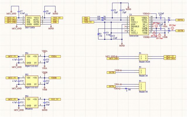
In the real board, I used jump wires passed the isolator U2 and 5V-5V converter PS3. And rest of the schematic is the design I applied to the boost converter test.

Regards,

Danilo

  • Hello Danilo,

    Thanks for reaching out on E2E.

    While it is important to take the supply transformer into consideration, as long as there is good supply filtering it is unlikely that it is the cause of the unusual waveforms you are seeing. To confirm this you could try increasing the VDD,VSS bypass capacitance, making sure to keep a small, low ESR capacitor as close to the driver pins as possible. This should smooth the VDD voltage, reducing any issue caused by oscillation on the supply.

    If changing the capacitance does not make a difference I would suggest looking at the gate drive path. Is it correct that you are using 0 ohm gate resistance? This could allow a lot of ringing to reach the driver, causing the issue you describe. 

    Could you provide waveforms both in normal operation, and when the device is failing, measuring VDD, the output, and the switch node?

    Please keep me updated on any progress.

    Regards,

    Daniel

  • Hi Daniel,

    Thank you for your response. According to our customer,

    I just came up another questions on TIDA-01159. Because of the shortage on the UCC21520, I bought several UCC21540 and gave a try on TIDA-01159. I made two TIDA-01159 boards with UCC21540 chip. One of them is working fine while another one does not. The bad one may lose gate signals when the driver running more than 5 mins. Later, I change the bad board with a UCC21520 chip, it works good again. I wonder if UCC21540 a good substitute to the UCC21520 on the TIDA-01159 design.

    Regards,

    Danilo

  • Hi Danilo,

    The UCC21540 should work in place of the UCC21520 in this design. The key difference between the two devices is the maximum voltage on both the primary and secondary side.

    The UCC21520 can handle voltages up to 20V on the primary side, while UCC21540 has an absolute maximum of 6V, with a recommended voltage of 5.5V. 

    Is it possible that the supply used in testing is approaching 6V, even for a short time? This could explain why the device fails after a time, and why the UCC21520 does not fail.

    A solution to this would be to make sure the input to the reference design is well regulated to below 5.5V.

    If you can provide information on the failure mode of the UCC21540 device, I may be able to help further. Are there any shorts between any of the pins? Has a new UCC21540 been tried on the bad board?

    Regards,

    Daniel