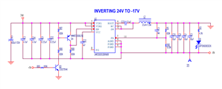
I built an inverting buck boost regulator using an LMR36015. It is converting +24V to -17V. It won't start from a fully-off state. When I turn off power there is a brief burst of operation. If I reapply power while it is generating -17V it will continue to run. Here is the schematic. The design values were obtained from the TI web based power supply design tool. I have tried adding a reverse clamp on the output using a Schottky diode. It did not change the behavior.
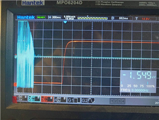
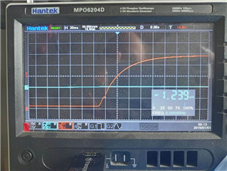
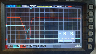
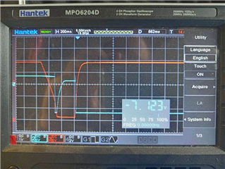
Condition: shown regular case, -17V doesn’t start. RED: 24V input BLUE: -17V
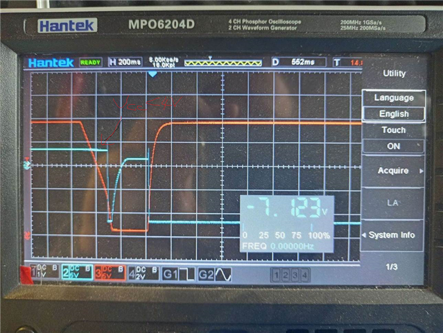
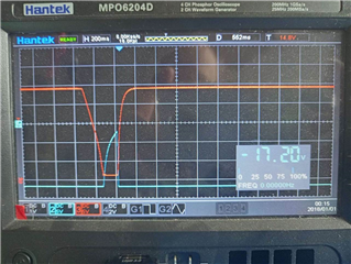
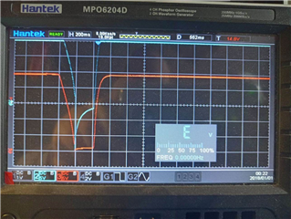
Condition shown: -17V works fine after power cycling, RED: +24 input BLUE: FB pin
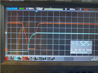
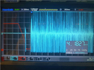
Condition shown: -17V was operating well, toggling input power quickly and it continues to run. RED: +24 input, BLUE: -17V
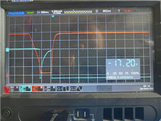
Condition shown: -17V was operating well, toggling input power with delay and it won't start, RED: +24 input, BLUE: -17V
Condition: captured on power recycling, after this switch -17V starts operating -17V – BLUE, 24V input – RED
VCC pin – BLUE, 24V input – RED
ENABLE: – BLUE, 24V input – RED
Condition shown: U3 starts working after power cycling, RED: +24 input, BLUE: SW pin
Condition shown: U3 doesn’t work after power cycling, RED: +24 input, BLUE: SW pin