We are using UC2827-(Voltage fed ) in one of our application. In that, we were trying to measure the loop gain phase response of buck converter. During testing, we faced some issues for measuring loop response of the designed circuit. Herewith, I briefly explained the issues which we are facing right now. So Kindly provide your feedback and suggestion on this.
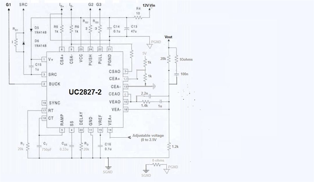
Simple voltage control loop method(as you mentioned in application notes) implemented with Type 3 loop compensation as mentioned in Figure 1,
Figure 1 : Error compensator-TYPE 3 method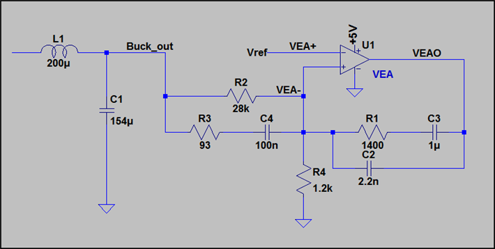
For the above mentioned error amp compensator, simulated loop response was shown in Figure 2
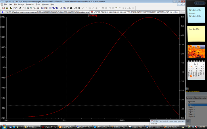
Figure 2 : Error compensator -feed back loop response
And also attached the expected loop response (simulated in LTSPICE)with this.
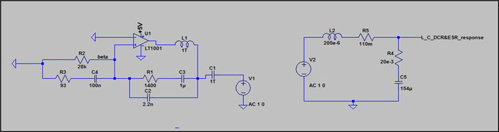 Figure 3 : AC anlysis simulation
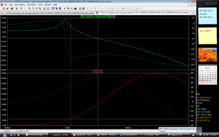
Figure 4 : Loop gain response (green -Loop response(LC response and compensator response) & Red: Compensator response
Note:In this simulation, modulator gain was not considered, only LC filter response and error amp compensator response are considered.
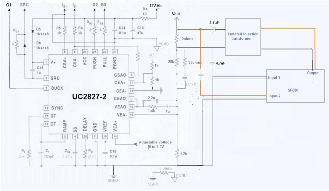
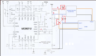
During practical testing, To measure loopgain – Following test set up was arranged as shown in Figure 5, where SF880 FRA was used to measure the loop gain response of UC2827 .
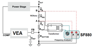
Figure 5 : Test setup with UC2827 for loop gain measurement
Injection voltage across 10Ohms was measured and observed that 150 to 200mV for 100Hz to 100kHz.
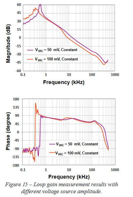
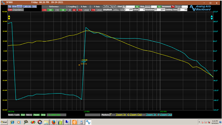
Loop gain response was measured using SF880 with the above mentioned setup -Refer Figure 6
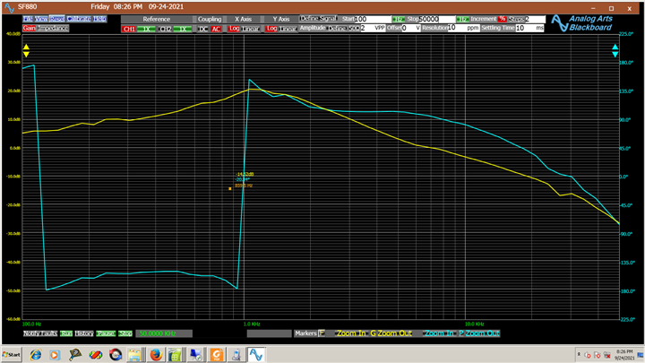
Figure 6 : Measured loop response(yellow-magnitude plot & blue-phase plot)
you can see in the above bode plot-Figure 6, phase response is going from -180deg to +180deg.
I dont an have idea, why phase response of loop gain is shunting like this.
Note: Same way, i measured the loop response of feedback path( passive components only) using SF880. the observed result was same as expected result (seen in the simulation).
Is anything wrong in my setup or feedback circuit.??
It would be better, if you guide me to find a right solution for the above mentioned issue.
Please do the needful.
Regards,
Vairavan P