This thread has been locked.

If you have a related question, please click the "Ask a related question" button in the top right corner. The newly created question will be automatically linked to this question.

UCC28810EVM-003: LED driver

Part Number: UCC28810EVM-003
Other Parts Discussed in Thread: UCC28811

Hi TI,

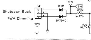
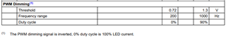
I just wanted to understand how External PWM Work in UCC28818EVM Circuit ........That header setting I have seen In datasheet.... But I wanted to know how this External PWM Control the LED here in this ckt.

  • Hi Amol,

    Can you provide a little more information as to what you want to know? 

    Also, what document and figure number did the screen capture you provided from?

    Thank you,

    Ray

  • I am working On LED driver For that I am referring IT Part UCC28810EVM-003 circuit ..In that Circuit there is three stage I wanted to understand in stage two PWM control externally ….That header setting I have seen In datasheet that I understand.... But I wanted to know how this External PWM Control the LED here in this ckt.

  • Hi Amol,

    For PWM dimming, a 0.72V to 1.3V, 200kHz - 1000kHz signal is applied to J4-3/2 using the duty cycle of that signal to control the output current.

    This table from UCC28810EVM-002 is more complete than the one in -003

    By providing PWM pulses to the Vsense pin, the UCC28811 is enabled/disabled at 200Hz to 1000Hz rate.  The output current (hence dimming) is controlled by the duty cycle of the PWM pulses.  Note that 0% duty cycle is highest LED current (brightest), and 90% duty cycle is lowest current (dimmest).

    Regards,

    Ray