This thread has been locked.

If you have a related question, please click the "Ask a related question" button in the top right corner. The newly created question will be automatically linked to this question.

TPS563249: Over voltage conditions

Part Number: TPS563249
Other Parts Discussed in Thread: TPS62913

We found issue in one of our field returned device. Our Front end module of WIFI IC is getting damaged at it's power pins.

We can replicate this issue by providing 6V to our Front end Module IC.

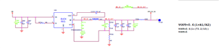
This Front end module is powered up (5V) with TPS563249DDCR switcher IC. For switcher IC input voltage is 12V and required output voltage is 5V.

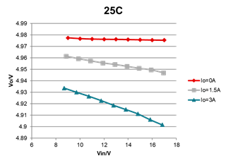
We need to understand under which conditions our switcher IC will exceed it's output voltage limit.

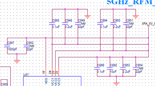
attaching the circuit for your reference.

  • Hi Pandey

    Here are my comments:

    1. How many WIFI ICs out of total was damaged at its power pins? I am not sure whether the damage is caused by the WIFI IC itself.

    2. Could you please capture the input voltage of the WIFI IC if it is possible.

    3. The target output voltage of TPS563249 is 5V, it is hard to go to 6V since there is OVP. I will check the protection point and feedback to you once I get the data.

    4.If the wire from TPS563249 to the WIFI IC is long and there are not enough input capacitors to the power pins of the WIFI IC, there may be large ring in the input voltage of the WIFI IC that will damage the IC. 

    Thanks.

    BR

    Ruby

  • Hi Ruby,

    Please find above mentioned comments response: 

    1. How many WIFI ICs out of total was damaged at its power pins? I am not sure whether the damage is caused by the WIFI IC itself.

    We have used two WIFI IC. We Found random damage sometimes both IC got damaged and some times one of the two. For our 5V switcher these two WIFI IC are the only Load. 

    2. Could you please capture the input voltage of the WIFI IC if it is possible.

    In the faulty devices 5V rail is getting short. So we can not measure the voltage at the Pin of WIFI IC.

    4.If the wire from TPS563249 to the WIFI IC is long and there are not enough input capacitors to the power pins of the WIFI IC, there may be large ring in the input voltage of the WIFI IC that will damage the IC. 

    Switcher IC is not placed far from the WIFI IC. We have provided proper decoupling capacitor at the power pin of the WIFI IC as well please find in the attached Image.

  • Hi Astha

    Is there any good WIFI IC so that you can capture the waveform of the TPS563249's output voltage and load current when using WIFI IC as a load. I am wondering if the load current has transient and cause a spike in the voltage.

    BR

    Ruby

  • Hi Ruby,

    We have checked the ripple in 5V rails and found following results:

    5V_Switcher_ripple.zip

    In Swither TPS563249DDCR datasheet we are not able to find PSRR. Please share PSRR value for the same.

    We have raised query for under which circumstances switcher will violate the expected voltage i.e 5V.Please response over this as well. 

  • Hi Astha

    1. Would you please do me a favor to give me the zoom in waveform especially the current waveform (input current of the WIFI IC, it seems that there is load transient here) and the picture of the test set up (to make sure that you use the smallest test loop, see the picture below). 

    2. For PSRR, you can refer to the line regulation below.

    3.For the Vout float up, as I have mentioned before, if the load current drops, the output voltage will get high. So when there is a load transient, the voltage spike may be a risk to the WIFI IC, this is why I want you to confirm the input current of the WIFI IC.

    4. One you confirm that, there is load transient here, there are several methods to reduce the spike: A. Add a cap in parallel with R7252; B. enlarge the output cap of the TPS563249

    Thanks.

    BR

    Ruby 

  • Hi Ruby,

    Please find the attached zoomed image for ripple.

    FEM_5V0_RIPPLE.zip

    We have checked our WIFI front end module is consuming min 15mA and Max 425mA. When we are transmitting maximum power in both RF chains (i.e both front end module is operating at full load) then it is consuming 700mA-800mA current.

    Please share the PSRR value or PSRR curve as per the following attached image.

  • Hi Ruby,

    Please find the attached zoomed image for ripple.

    3051.FEM_5V0_RIPPLE.zip

    We have checked our WIFI front end module is consuming min 15mA and Max 425mA. When we are transmitting maximum power in both RF chains (i.e both front end module is operating at full load) then it is consuming 700mA-800mA current.

    Please share the PSRR value or PSRR curve as per the following attached image.

  • Hi Astha

     There is a voltage spike of the input and the max value can be 5.93V which may be a risk to damage the WIFI IC. I would recommend to add a 22uF cap to the input of the WIFI IC and after that please do me a favor to capture the waveform with full load - 27db on both RF chains to check whether there is any improvement. Also, please make sure that the 0.1uF cap is close enough to the input pin of the WIFI IC.

    For PSRR, I did not find the PSRR curve in our test because usually DCDC's PSRR is not that good. We actually have device target good PSRR which is TPS62913.

    BR

    Ruby

  • Hi Ruby,

    In 5V switcher output we have mounted two 22uF capacitor.

    All ripple readings are shared with same capacitor.

    We have measured the ripple with full load(27dBm) output power, and we get 125mv peak to peak voltage, it is bit difficult for me to understand in which condition it will reach to 5.9V. Please explain your point briefly. 

  • Hi Astha

    Yes, I know that there are two 22uF capacitors in the output of TPS563249. But there are parasitic inductor when it supply to the WIFI IC. Also the current of the WIFI IC is changing, and you have two WIFI ICs here, we do not want these two ICs affect each other when the current is changing, so the input cap for the WIFI IC is needed and make sure the input caps are close to the power supply pin to the WIFI IC. I would recommend to change the C950 from 2.2uF to 22uF as well as C948.

    Sorry, it's my fault. I missed the decimal point, I thought the peak was 900+mV. Yes, you are right, the voltage spike is limited as is seen in the waveforms you share. 

    To conclude, the waveforms you share have no problem, and I cannot see any risk here. But I can share some methods to reduce the voltage spike:

    1. Add Cin for the WIFI IC

    2. Add a zener diode to limit the max input voltage for the WIFI IC

    3. Keep the board clean, especially clean the  flux / contamination, the flux / contamination can be conductive.

    Thanks.

    BR

    Ruby

  • Hi Astha

    Add another comment here:

    Do you have any idea about the voltage tolerance of the input caps for the WIFI IC? And the output caps voltage tolerance for TPS563249? If the voltage tolerance is only 10V, the derating should be considered.

    BR

    Ruby

  • Hi Ruby,

    Yes we have used the10V rating capacitor at power pin of WIF Front end module.

    We have tested  the rating of these capacitors in some of our field retuned devices and there is no such variation in capacitance.

  • Hi Astha

    The value of the cap will drop when there is a DC voltage adding on the cap. When there is no voltage across the cap, the variation is not significant.

    BR

    Ruby