This thread has been locked.

If you have a related question, please click the "Ask a related question" button in the top right corner. The newly created question will be automatically linked to this question.

UCD3138: UCD3138 Bridgeless pfc FDPS

Part Number: UCD3138

Hello,

I need to design 2kw bridgeless pfc using UCD3138. I have installed FDPS. What are the changes that i need to make in the hardware part to obtain the required design.

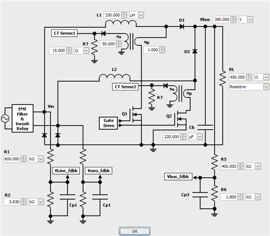
I need the calculations for Sense resistors R1,R2,R5,R6,R7 and turns Ns,Np. How to make the required calculations??

  • Mownika, I assume that you will use the same input and output voltage ranges as the existing design,  I suggest that you use the same resistors in the voltage measurement circuits as are used in the existing design, because you won't have to change the EVM firmware constants for voltage that way.  

    For the sense circuits which are measuring current, the guideline is to have the signal fit into the range of the input with some extra overhead for overcurrent events.  The ADC12 has a range from 0 to 2.5 volts, and the EADC has a range from 0 to 1.6 volts.  

    You will need to change some constants in the firmware to adjust the current and power out measurements to reflect the new scaling of the ADC signals.  

  • Hi Ian,

    My input requirement is 230V Ac and output is requirement is 400V dc. I need to make calculations according to that. I have'nt found any documents related to this bridgeless topology. I need to change R and c values accordingly.

  • I believe that the documents are the user guide for the EVM and the source code provided by TI.  

    The existing code is designed for something like 100 to 260 volts in and about 400 volts out, so the voltage measuring circuits should be the same.  

    The current measurement circuits need to changed as I described.  You will probably use different current transformers as well.  It's a simple application of Ohms law otherwise.  You need to have the voltage at your maximum current be a safe margin below the maximum voltage for the EADC or the ADC.  

    It is a good idea to have the output impedance of the circuit at 1 K ohms or so for the ADC if you want maximum accuracy.  

    I'm not sure about the capacitors in the measurement circuits.  They are probably used for filtering, so you need to consider your need for bandwidth vs noise.