This thread has been locked.

If you have a related question, please click the "Ask a related question" button in the top right corner. The newly created question will be automatically linked to this question.

TPS53015: Schematic review request

Part Number: TPS53015

Hi, 

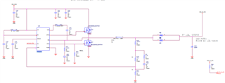
Please review the attached schematics and let me know your valuable comments.

Vin = 24V normally
Vout = 5V, 12A

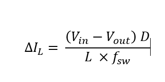
Please review specially the feed back resistors and Inductor calculation.

I am little bit confused about the inductor calculation. I need to design the same for 3.3V and 12V supplies. 

  • Hello,

    I took a look at the schematic and would have the following suggestions:

    1. I would recommend that C249 be a 10V, 4.7uF capacitor. The current capacitor selected is rated for 6.3V and the capacitance will de-rate significantly when the DC voltage from the VREG5 pin is seen on that pin

    2. Please note that C250 should be placed as close to the VIN pin of the device as possible. I would also recommend a 0.1uF, 50V, 0402 high frequency bypass capacitor connected between VDD_DCIN and PGND placed as close to the drain pin of Q18 as possible. At 24Vin, I also recommend 50V input capacitors.

    3. I would ensure C254 is rated for 25V minimally in this application.

    4.  The inductor ripple in this application is quite high (approximately 8A for a 12A rail). I would recommend a 2uH inductor at a minimum for the 24Vin, 5Vout application

    5. The feedback resistors are acceptable for a 5Vout application generally. The current selection will regulate to approximately 5.09V if that is acceptable for this design. I would recommend 0.1% tolerance if possible as well, but that is not necessary if the design has some tolerance in the output voltage.

    In regards to the inductor selection and inductor ripple current, TI typically recommends that the inductor ripple current for the TPS53015 be approximately 30% of the load current in a balanced design.

    The inductor ripple current may be calculated as follows:

    In this application Vin=24V, Vout=5V, fsw=500kHz, D= 5/24 (approximately). In this case L should be selected such that the inductor ripple current is around 3.6A (0.3*12A) if following the recommendation. While this is not 100% necessary, 8A of inductor ripple is quite high and will result in lower efficiencies, higher output ripple, and loss in the inductor. 

    Please reach out with any further help needed.

    Regards,

    Alec Biesterfeld