This thread has been locked.

If you have a related question, please click the "Ask a related question" button in the top right corner. The newly created question will be automatically linked to this question.

LM2705: supply two parallel LED strings

Part Number: LM2705

Hello Team, 

my customer wants to use LM2705MF in his display application as a backlight driver. They use the driver already in another application:

Since I'm unclear about the functionally of the controller I would like to know if we can use it in the following configuration:

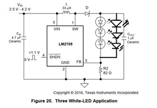
The LED line is divided into 2 x 3 LEDs in series in parallel and the max current on both strings will be 40mA. This means that the 3 LEDs (6LEDs) are part of the control loop. How is the resistance, which is given here with 82 ohms, calculated or how do you get the 82 ohms? What current does this set up? And how does the control with the PWM via the shut down pin work? In addition, we would like to operate the controller with 5V at the entrance, which according to the data sheet should not be a problem. Why in this application, the voltage range is limited to 4.2V? Would be great if you could also provide a small description of how the IC works. As I said, I am not quite clear about the operating principle for this application.

Thank you 

Jan 

  • Hi Jan,

    The 82ohms is calculated from led current, because the FB voltage is 1.237V (typ), the led current is 1.237V/82ohms = 15mA. the chip will always try to regulate FB pin voltage to 1.237V, so the resistor value is 1.237V/ total led current.

    LED diming can be set by PWM through SHDN pin, adjust PWM duty cycle to change the diming. Because the chip has several ms start up time, this PWM frequency should not be very high. It is recommended to set to several hundred Hz.

    The image is just one application, the input voltage can be 2.2V-7V. 

    Best Regards,

    Eric Yue

  • Dear Eric,

    thanks for the response.

    One more question regarding the inductor. When using 5V as input voltage are 33µH still OK or should we use a lower value?

    Regarding the dimming? When using the SHDN pin the start up time is not relevant anymore, right. So the start up time is just relevant for the power cycle?

    Thanks and best regards,

    Stefan

  • Hi Stefan,

    33uH is still ok to have a relatively small current ripple.

    The start up time means when SHDN pin changes, the chip need some time to output normally, therefore the PWM frequency cannot be set very high for better dimming performance.

    Best Regards,

    Eric Yue

  • Dear Eric,

    thanks for your response.

    Can you recommend any typical value for the frequency of the PWM?

    Thanks, Stefan

  • Hi Stefan,

    I think 500Hz is okay, and you can adjust this frequency by experiment testing.

    Best Regards,