Hi,
I m using the UCC2818 TI part to manage the PFC converter.
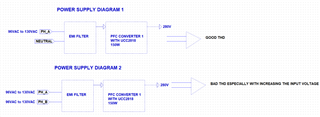
PFC converter is used on CCM mode and has theses features : Vin = 96VAC to 130VAC, VOUT=280V, Pout=150W
When I connect the PFC between neutral and line, i have a great THD. BUT when i connect it between two lines (PHASE A and PHASE B) the THD is severely degraded.
I tried to change the current and voltage loop components but the harmonic distortion is still bad...
Do you have any idea how can proceed to have a great THD ?
Thank you for your support
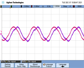
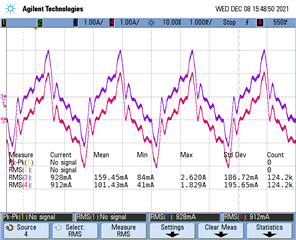
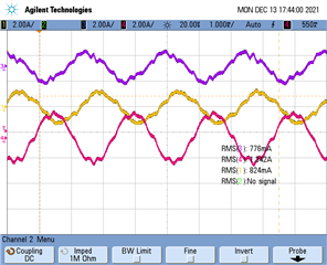
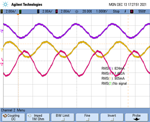
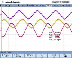
Here two pictures :
First one : RED Current measurement with PFC connected between Neutral and Phase A
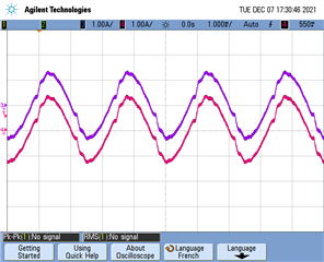
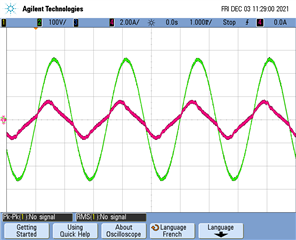
Second one : current measurement with PFC connected between Phase A and Phase B