This thread has been locked.

If you have a related question, please click the "Ask a related question" button in the top right corner. The newly created question will be automatically linked to this question.

TPS6508700: Use With Non AMD Processor

Part Number: TPS6508700
Other Parts Discussed in Thread: TPS650864, , TPS650861, IPG-UI

Hi,

 I am a university student. This year is my graduate year and I'm making a graduate project. My project is an FPGA-based SOM(System on module). I am using the Trion T120F576 FPGA chip of manufacturer Efinix Inc in my project. I want to design with a single PMIC in SOM. I was going to choose PMIC as TPS650861 or TPS650864. But I could not supply both of them due to stock problems through my supplier DigiKey. So I procured the TPS6508700 and thought of configuring it according to the project. 

 I will run the PMIC with 5V. For this, I will use a small boost converter for VSYS as specified in the datasheet of the same silicon TPS650861. For SOM, I need voltage levels like 1.2V, 1.25V, 1.8V, 2.5V, 2.8V, 3.3V. I intend to do this by configuring buck controllers, buck converters, and LDOs according to power requirements. 

 As far as I understand, the only difference between PMICs such as TPS650861, TPS650864, TPS6508700 with the same silicon is the configuration data pre-written in the OTP memory (if wrong please correct me). The TPS6508700 is also configured according to the AMD system. 

So, I want to learn these:

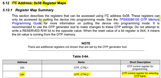
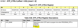
-The PMIC configures the voltage rails according to the data in the OTP memory at every start. So, do the values we write to the registers via I2C become permanent? If we make a new configuration once, does this apply at every start? Or will the PMIC start with the OTP memory at every start, and then configure it via an external microcontroller, etc., and I2C? 

-So, are the EN S0, GPIO_G3, and EN S5 power states specialized for AMD SOCs?

Based on your answer, I can go two ways for SOM:

1- Post-production, providing PMIC supply voltages and I2C connections using test points and making a single initial configuration (by making the necessary power isolations). And also, controlling the CTL pins with Pull up resistors. 

2- Adding a pre-programmed small package MSP430 as a general controller to the design and initializing the initial post-power I2C configuration. After configuration, start the system again via MSP430, using EN S0, GPIO_G3, and EN S5 power states or in another way.

I am waiting for your answers. Good work, best regards.

  • Hello Eshab,

    I have assigned this thread to a product expert. Please expect some delay on the answer due to US holiday today. 

    Thanks.

    Regards,

    Tomi Koskela

  • OK, I am waiting.

    Thanks.

  • Hi Eshab,

    Thanks for your patience! The TPS6508700 PMIC was configured specifically to support AMD Family17h Models 10h-1Fh processors. For a custom OTP config, we recommend using TPS650861 which is comes with two memory banks that can be programmed to meet specific power requirements. 

    TPS6508700 can technically be re-programmed because even though one of the memory banks comes pre-programmed by default, the second one should be blank and available for programming. We do not recommend this option as TI will not be responsible for any production material that is modified. Changing the default programming on TPS6508700 production material to match a different OTP config is not an approach we have validated. However, we have a programming BoosterPack available that you could use to try and re-program the inventory available to validate the target OTP configuration and make sure it works before it is implemented in the actual board. Below are some useful links to get familiar with the programming process. As an additional note, after changing the OTP registers,  additional steps must be followed to burn the changes into the OTP so they become the new power-up defaults. 


    Thanks,

    Brenda

  • Hi Brenda,


    Thank you very much for your answer. I checked what they shared. However, there is one point that I do not fully understand.

    There are two banks of OTP memory inside the device and one is pre-programmed according to AMD SOCsI will program the second one. So, how does the device know which OTP will load its data into the registers at power-up? How do we change the power-up defaults from bank "0" to bank "1"? What "additional steps" are you talking about?

    Thanks,

    Eshab

  • Hi Eshab,

    Just for your reference, that information can be found in the technical documentation available in the TPS650861 product folder (please refer to datasheet, programming guide and boosterpack user's guide links in my previous message). This PMIC has a "pointer" that allows the users to switch from OTP bank 0 to OTP bank 1. As stated in the TPS650861 datasheet, to select the second memory bank, the "OTP_BANK" bit on register "OTP_CTRL2" would have to be changed from from 0 to 1. This can easily be done by using the Device Controls tab in the IPG-UI software (see section "4.4 Program The Device Using IPG-UI EVM GUI" in the BOOSTXL-TPS650861 EVM User’s Guide). 

    Please note, the switch to the second OTP bank is permanent as the pointer bit is also OTP. 


    From the Register Map in the datasheet:


    OTP_CTRL2 bit description

    Thanks,

    Brenda

  • Hi Brenda,

     Thank you very much again. I found answers to all my questions. I'll open a new thread if I run into problems though. The bank selection had never caught my eye on the register map until you pointed it out.

    Good works, best regards,

    Eshab