- Ask a related questionWhat is a related question?A related question is a question created from another question. When the related question is created, it will be automatically linked to the original question.


For the design and control of a full bridge weinberg converter (full bridge boost with start up winding, hard switched), we are planning to use UCC28220-Q1 to control the two full bridge legs 180 degree out of phase.
Startup mode is using the converter as a flyback (full overlap on all switches).
when the voltage reaches a certain threshold, the converter will go into boost mode, creating overlap by being in the range of 50-100% duty cycle. This is partly enabled by the PWM controller, but also external hardware.
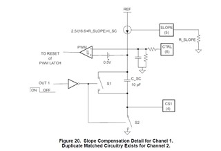
The slope compensation is only wanted, when the switches overlap, and therefore it is needed to be created externally to the PWM controller, with an emitter follower adding the slope compensation to the measured current signal.
When browsing the datasheet, internal slope compensation graph shows the relation between slope compensation and resistor value.
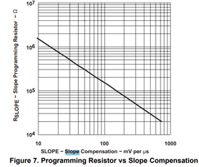
Is it therefore correctly understood, that when not adding any resistor to the slope compensation circuit, that no slope compensation will be added? Or is 10mV per microsecond the lowest possible?
Is it possible to leave it open (no resistor connected)? What will happen?
Best regards,
Jesper Carlsen