This thread has been locked.

If you have a related question, please click the "Ask a related question" button in the top right corner. The newly created question will be automatically linked to this question.

UCC28019: Transient Response (Inductor waveform)

Part Number: UCC28019

Hey

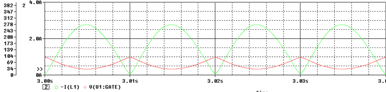
I am simulating the transient model of the UCC28019 for PSpice and haven't quite been able to understand the nature of the inductor current and gate voltage. Simulating the circuit provided by TI without any modifications, shows the inductor current nature more like CrCM rather than CCM (*Inductor current in green and Gate voltage given in red).

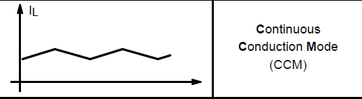
I expected that the gate signal would have a nature similar to that of a square wave, and the CCM inductor waveform would look like below

  • Hi Ritu,

    TI provides an average model not a switching model for the UCC28019 to provide a quick simulation of the output based on load and line transient conditions. Because it is an average behavioral model, you won't see the same signals that you'd expect in a cycle-by-cycle (switching) simulation. It is unfortunate that the model uses the actual pin name "GATE" where you would expect to see something like a 0V - 5V square wave driving the gate of a MOSFET, but instead has a signal which is more internal to the function of the controller.  This is the same reason why you don't see the expected ripple current through the inductor.

    Since the switching frequency is 65kHz and the AC line frequency is 50/60Hz with an even slower voltage loop, cycle-by-cycle simulations would take a very long time.

    I hope this helps.

    Ray