This thread has been locked.

If you have a related question, please click the "Ask a related question" button in the top right corner. The newly created question will be automatically linked to this question.

UC3525A: error amplifier question

Part Number: UC3525A

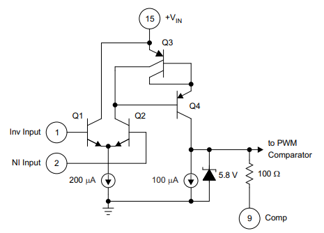
If the V+ (P15) = 30v, the N.I.INPUT(P2)=30v and there is 20k ohm resistor between  p1 and p 9. So could the INV.INPUT(p1) get 30v ~? 

  • Hello John,

    These conditions are not outside the recommended operating conditions: +VIN (pin 15) = 30V, NI INPUT (pin 2) = 30V, with 20k from COMP (pin 9) to INV INPUT (pin 1).

    However, examining Figure 8 from the data sheet, I see a 5.8V clamp on the COMP pin.  So the INV INPUT cannot reach 30V because it depends on COMP voltage.

    The maximum voltage from the COMP pin is shown in the EC tables

    Regards,

    Eric

  • Hi Eric,

    I can understand the max inv input will be limited by the 5.8V clamp voltage. However  there are other questions below: 

    1. Is there good solution to boost the inv input through adding peripheral circuit ?

    2. Is there a solution to make the Input Threshold reaching zero volt at zero duty-cycle?

    Best ,

    John

  • Hi John,

    1. Is there good solution to boost the inv input through adding peripheral circuit ?

    I don't see any advantage to doing this.  The error amp should balance it's own inputs (i.e. close the loop) via its output.  I think forcing the (-) pin externally would defeat the control/regulation capability of the error amp.

    2. Is there a solution to make the Input Threshold reaching zero volt at zero duty-cycle?

    The input thresholds to the PWM comparator are 0.9Vtyp for 0% duty cycle, and 3.3Vtyp for maximum duty cycle.  These thresholds must be within the output min/max output voltages of the error amplifier:  0.5Vmax for low level, and 3.8Vmin for high level.  So, you don't want to change these thresholds.  The reason is the error amplifier cannot reach 0V.

    Regards,

    Eric