This thread has been locked.

If you have a related question, please click the "Ask a related question" button in the top right corner. The newly created question will be automatically linked to this question.

LM5022-Q1: LM5022 and control loop problem

Part Number: LM5022-Q1
Other Parts Discussed in Thread: LMG34XX-BB-EVM, LM5022, PMP22339, LM3524D

Good morning all,
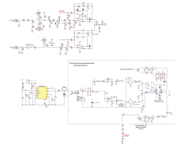
I am making a synchronous buck to make a CC-CV charger with an LMG34XX-BB-EVM evaluation board to test GaN modules from TI.
This board just needs a PWM input, this PWM is then reconditioned through the development board in order to correctly drive the 2 GaN transistors mounted in half-bridge, the one at the top of the bridge is the main switch of the Buck, the one bottom is used in freewheel.
To carry out the PWM control, I use an LM5022 (which I have on hand and given the current shortage of components...) which I divert from its initial function which is for Boost and Sepic use.
It works correctly and I get the desired result (Vin=200VDC -> Vout=150VDC), at least without load for the moment.
Here is my question:
I am working on closed loop control, for this I will do the feedback on the COMP pin (having set FB to GND) and I have opted for type II compensation.
I cannot find in the datasheet the amplitude of the sawtooth (Vosc) to fill in my equation for determining Rcomp.
Could you advise me on this?
If you had a concrete example of closed loop design with the LM5022, I'm interested, because in the datasheet it's really explained in a horrible way...
Thanks in advance.

  • Hello Jean-Yves,

    Thanks for reaching out to us via e2e.

    The sawtooth generator is a current source, therefore no definition of the voltage.

    Please refer to section 7.3.5 and figure 12 of the datasheet:

    The LM5022 generates the slope compensation with a sawtooth-waveform current source with a slope of 45 μA × ƒSW, generated by the clock (see Figure 12). This current flows through an internal 2-kΩ resistor to create a minimum compensation ramp with a slope of 100 mV × ƒSW (typical).
    The slope of the compensation ramp increases when external resistance is added for filtering the current sense (RS1) or in the position RS2.

    Best regards,

    Harry

  • Hello Harry,

    thanks for your reply.

    I use the same configuration as in PMP22339, that is to say that I do not use the FB pin but I act only on the COMP pin with the following schematic:

    I'm not sure that my picture is readable...

    If you have an email I could to send you the original file.

    The current information is taken by a current transformer and the voltage information comes from a voltage divider of the output Buck.
    2 diodes create an ORING which provides CC-CV regulation by acting on the PWM of the LM5022.
    I have read the datasheet (figure 12), but I do not use the CS pin for my regulation and I do not see what information to take for the Vosc amplitude necessary for my calculation (Vosc being supposed to be the amplitude sawtooth).
    Based on what I understand from your answer, the amplitude would be 100mV with a slope of 100mV x 10µs (@Fsw=100kHz).
    But looking at the simulation I made from the internal diagram on page 9 (7.2 Functional Block Diagram), I tend to think that my Vosc=1.2V approximately.

    What do you think about this?

    Best regards.

  • Hello Jean-Yves,

    The sawtooth signal you are looking at is only used for the slope compensation.

    If it was above 0.5V (1.2V, as you state), over current comparator would permanently be tripped.

    Regards,

    Harry

  • Ok, so I don't know how to drive the control loop with this LM5022.

    Have you an example for understand the method with this IC?

  • Hello Jean-Yves,

    The LM5022 is meant for Boost converters and it has certain features built in for that purpose.

    I am not sure if you can use the part in your intended way.
    E.g. I don`t think that the slope compensation can be disabled at all. 

    Anyway, I have forwarded some questions to our specialists in the US.
    But it may take some days until I will get a feedback.

    Regards,
    Harry

  • thank you Harry for your interest in my problem.
    I think it is possible to use this circuit in Buck mode, because after all the circuit is supposed to react according to an error correction without the need to know the topology in which it is used.
    No worries about waiting a few days for your expert's return.
    thanks again

  • Hello Jean-Yves,

    I want to apologize for the late reply. It was difficult to find someone who could give me a hint how to maybe accomplish what you are trying to do here.

    [You wrote:]
    > I think it is possible ... because after all the circuit is supposed to react according to an error correction without the need to know the topology ...

    In principle you are right, but I was less thinking about the topology but more about some of the integrated features which cannot be disabled.
    And this is exactly the problem that has now been confirmed by the expert that I was talking to.

    [I wrote (internally):]
    > the current of the ramp generator flows through an internal 2-kΩ resistor to create a compensation ramp (voltage).
    > This voltage is not only fed into the positive input of the CS comparator, but also into the positive input of the PWM comparator.

    [Here is the reaction of the expert:]
    That’s a good catch. The slope compensation ramp (45uA) does play a role in the PWM comparator.
    With the CS pin connected directly to GND, the ramp signal is at most 90mV, which means that the duty cycle seems to be terminated quickly,
    since the negative input of the PWM comparator is much larger than the positive input of the PWM comparator.

    I’m going to give my best assessment on how to fix this.
    With FB connected to GND, COMP is pulled up to 5V. This can be adjusted using the CC-CV loop that the customer has built.
    The input to the PWM comparator is sampled such that the COMP voltage is offset by 1p4V, and then divided by 3, so 1p2V will be seen at the negative input of the PWM comparator.
    I believe this voltage will be the steady-state voltage when regulating.
    [My comment:  The 1.2V that you were also talking about]

    [My comment:  Here comes the first thought of the expert, but as I had already stated in an earlier e2e post, it cannot work this way. I left it in anyway.]
    I think that in order to properly compare and terminate the cycle, there needs to be a ramp large enough such that when COMP hits the ramp voltage, the cycle is terminated.
    I think the best way to implement this is to add a resistor from the CS pin to GND in order to generate a ramp.
    We can use the formula: 45uA*(2k + R_cs) = Vramp, so the Vramp should be larger than 1p2V.
    The problem with this is that we will trigger current limit, since current limit threshold is 0p5V.

    [My comment:  The only thing left that you might want to try is the following:]
    Theoretically, what we should do is somehow pull COMP pin voltage low enough such that the voltage at the negative input of the PWM comparator is lower than 0p5V-
    at which point we can control the duty cycle, without triggering current limit.

    So to do this, I think a quick and easy solution is to use a Zener diode at the COMP pin.
    I say a value of 2V is ok, since it’s easy to calculate the value at the PWM comparator negative input, which is 0p2V.

    Therefore, the max value of Vramp should be larger than 0p2V, but less than 0p5V at 45uA current,
    so you should pick a value from the resistor of CS pin to GND in between 2.4kOHm and 9.1kOhm,
    where 2.4kOhm gives you max ramp voltage of 0p2V, and 9.1kOhm gives you max ramp voltage of 0p5V.

    This is just my guess, but it might be the best thing I could come up with.
    [End of the expert's comments]

    So, to be honest, using the LM5022 would probably cause you more trouble than you might expect.

    What you are actually looking for is a simple PWM controller with the following functionality:
    - compare the feedback signal to a fixed reference voltage
    - turn off the output when the feedback exceeds the reference
    - turn the output back on at the beginning of the next cycle

    We have such parts in our portfolio. Also, most of the Buck controllers will do the job (but be careful, some of them will also have extra features which might disturb you).

    In my opinion the LM5022 cannot really do that job in a reasonable way.
    So, if you decide to try the proposal of our expert (further above), I am afraid that I do not know how we could assist you any further.


    Best regards,
    Harry

  • Hello Harry,

    I will indeed use another circuit better suited.
    Maybe just an LM3524D that I've used on many occasions.
    Thank you to your expert and to you Harry for this well-constructed answer which allows me to better understand the LM5022 on which I will repeat these tests when I have a little more time.
    Cordially.