This thread has been locked.

If you have a related question, please click the "Ask a related question" button in the top right corner. The newly created question will be automatically linked to this question.

TPS62162: Unexpected Low Power Mode

Part Number: TPS62162

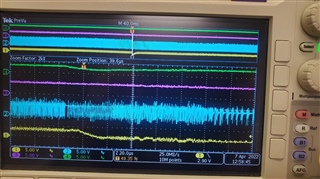
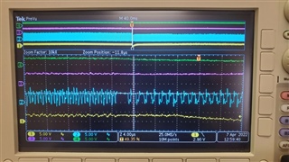
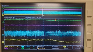
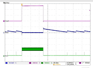
We have a system that undergoing testing.  When the system is operating is a steady state (no changes in power requirements) we introduce a physical shock of several hundred Gs.  When we observe the SW output signal we can see that it transitions to Low Power mode of operation, which immediately causes the regulated output (3.3V) to drop to about 1 volt before it switches back to PWM mode.  Through all of this there is no change in the input voltage.

Is there a way to force the regulator to stay in the PWM mode?  How can we determine what is causing the switch to Low Power operation.

Or is there a part that would be a better choice.

  • Hi Leslie,

    Could you give us the more detail about the physical shock of several hundred Gs? What is that? Please share the schematic, steady state condition and SW node waveformas well.

    Thanks,

    Nancy

  • The shock is basically a drop test from about 6 feet onto a hard surface.  We haven't measured the acceleration, but I would estimate that a 0.5 millisecond shock of around 20,000 Gs (kind of a standard thing I think).

    These show different zoom of the same capture:

    Top (yellow) is 3.3V, next (magenta) is +5V input, next (cyan) is SW and last (yellow) is the CPU reset signal.

     .

    Basic schematic with

    input capacitor is 10 uF

    output inductor p/n  TDK VLS201612HBX-2R2M-1

    output capacitor p/n LMK212 BJ226MG-T

  • Hi Leslie,

    Nancy will reply you next Monday!

    Shuai

  • Hi Leslie,

    Do you mean drop the whole test board from about 6 feet onto a hard surface? From the waveforms, it should not be DCM mode with 3.3V drops to 2.3V.

    The transition from CCM and DCM is very smooth and output voltage should increase a little bit to instead of dropping about 1V. See below waveform from datasheet.

    I am wondering if the device enters current limit. Could you probe the inductor current to see if inductor current increasing? The device could not disable DCM mode. You may try to add dummy load on the output or increase inductor value to make DCM current lower.

    Hope this helps,

    Nancy

  • Our entire system is mounted in a very robust metal enclosure and the entire system is dropped to a hard surface.  The board with the power supply is mounted on standoffs.

    In paragraph 8.3.2 "Current Limit and Short Circuit Protection" gives some hints at what I should see at the SW output when current limit is reached ... ". If the current limit is reached, the high-side FET is turned off."  To me this says that I should observe the SW output going to a low state.  Instead the waveform shows the SW output continuously on for a few microseconds.

    Also, I would expect to see a sequence where the output voltage begins to droop and then the SW output responds.  Instead the waveform shows the SW output going to a steady high state and then the output voltage droops.  When RESET occurs, the output load decreases (by system design).

    We are going to experiment with a larger inductor and larger output capacitor (3.3 uH and 47 uF). Also we will try alternate technology inductors rather than the wire-wound inductor we are using now.  The size of the pads for the components limits what we can do with our current system.

    I will post new wave-forms if we see any change in behavior.

  • I'm not sure how to probe the inductor current.  And making any temporary circuit that is mounted inside the system is difficult as it must be robust enough to endure the shock as well.  I'm open to suggestions.

  • Hi Leslie,

    The current limit is cycle by cycle limit and not shutdown the device. If the current limit 1.45A is reached, the high-side FET is turned off, the low-side FET is turned on to allow the inductor current to decrease, when the low-side FET decrease below the low-side FET current limit 1.2A, the high-side FET turns on again. So the from switching node, it is continue except off time is little bit long and cause Vout drop. 

    1. Yes, it is difficult to add current probe to measure inductor current. Could you add a small dummy load parallel with output capacitors? If the behavior becomes worse, it should be current limit. Please check downstream circuit if output current increase or not?

    2. To rule out DCM mode, you can increase the inductor to make 1/2 ripple current lower. So the device may not enter DCM easily.

    Hope this helps

    Thanks,

    Nancy