This thread has been locked.

If you have a related question, please click the "Ask a related question" button in the top right corner. The newly created question will be automatically linked to this question.

TPS7A20: TPS7A2028 Vout drop to -0.55V

Part Number: TPS7A20

Hi Sir,

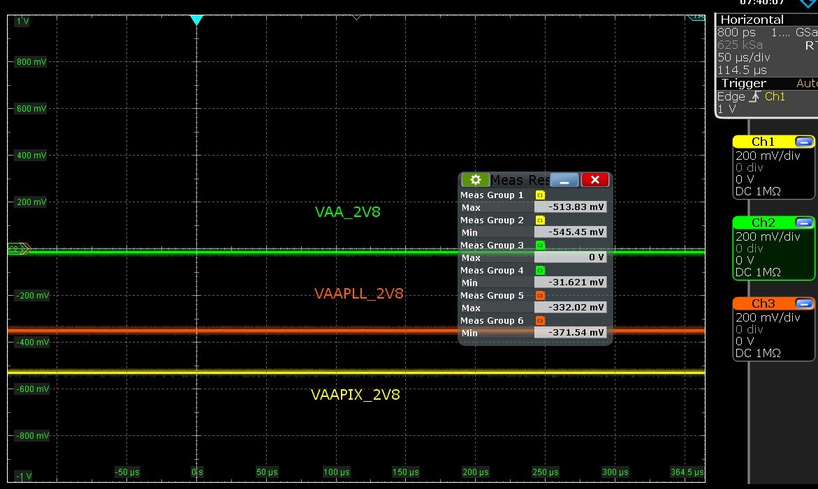
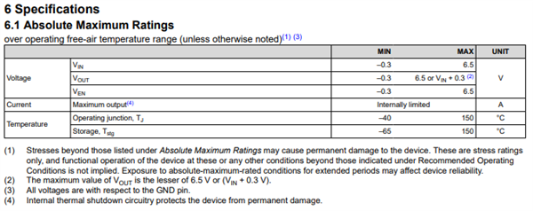
Will the IC be damaged if there is no power to the IC and -0.55V appears on the output pin?

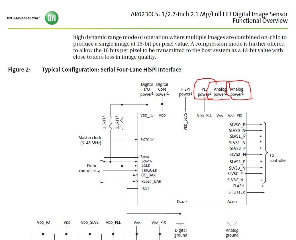
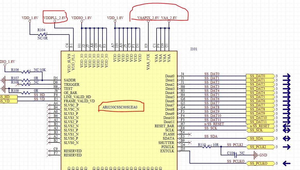
The 2.8Vout only apply the power to ON-SEMI CMOS sensor device.

But the Vout drop phenomenon while the sensor get the ambient light. (no power on the LDO and CMOS sensor)

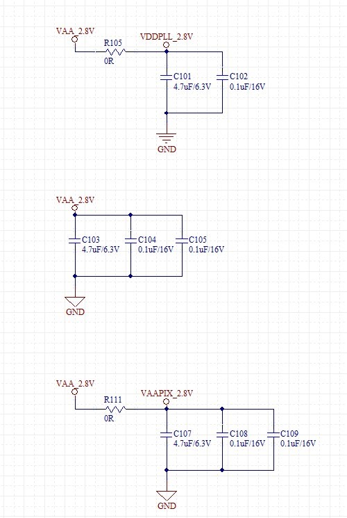
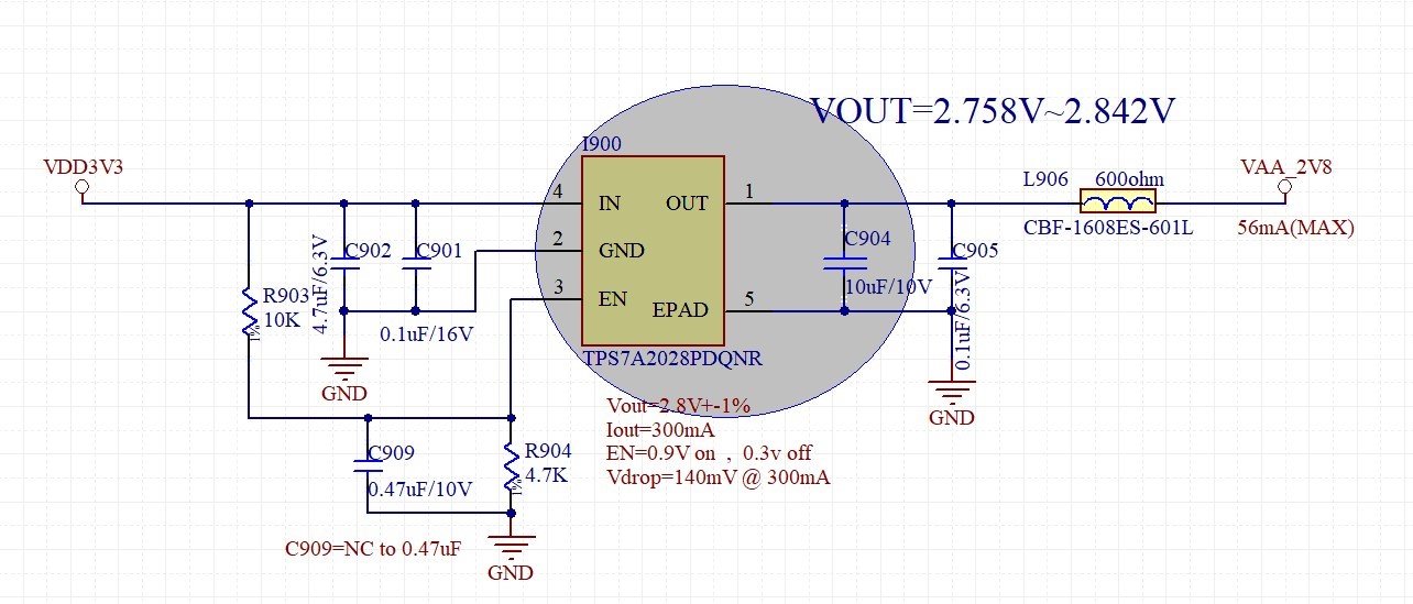
TPS7A2028 schematic:

Vout waveform:

  • Hey Henry, 

    The -0.55V Vout is below the -0.3V so there could be possible damage to the device.

    If the device is powered off and is producing -0.55V, maybe the load is pulling current from the LDO. 

    Does the ambient light turn on the CMOS sensor? What are the different signals on the scope shot? Is this result being observed by multiple units?

    Thanks,

    -Jimmy

  • Hi Sir,

    Does the ambient light turn on the CMOS sensor? => when the light turns up to 60K lux, the customer will get the -0.55Vout.

    What are the different signals on the scope shot? => the cmos sensor needs three power sources of 2.8V, see the below figure.

    Is this result being observed by multiple units? => the same cmos sensor.

    AR0230CS:

  • Hey Henry,

    For more clarification,

    What is Vout of the LDO when there is no ambient light?

    Where are the 3 signals being measured in relation to the LDO on the schematic? (VAA looks like it is on the LDO output after the inductor but before the CMOS sensor. Where is VAAPIX and VDDPLL?)

    Is this result (Vout=-0.55V) being observed by multiple LDO units?

    Thanks,

    -Jimmy

  • Hi Sir,

    What is Vout of the LDO when there is no ambient light? => no ambient light is 0Vout, the light turns up to 60K lux, the customer will get the -0.55Vout. Both Vout results are no power to the IC.

    Is this result (Vout=-0.55V) being observed by multiple LDO units? => No, there only used one TPS7A2028.

    Where are the 3 signals being measured in relation to the LDO on the schematic? (VAA looks like it is on the LDO output after the inductor but before the CMOS sensor. Where is VAAPIX and VDDPLL?) => Please refer to the below schematics.

    On-semi AR0230 schematics:

  • Hey Henry,

    If it is possible, could the customer test this result with a different LDO? It would be good to rule out the possibility of a damaged LDO producing these results.

    However, it seems like the problem is with the CMOS sensor rather than the LDO since the ambient light causes the changes in output. 

    Thanks,

    -Jimmy

  • Hi Sir,

    My customer knew the problem is with the CMOS sensor rather than the LDO. They will add an external circuit on LDO Vout to fix this issue.

    They would like to know what are possible side effects after the LDO Vout drop over -0.3V?
    How long time cause the LDO damage after Vout drops down to -0.55V?

  • Hey Henry,

    We recommend operating within the absolute maximum ratings specified by the datasheet to avoid damage to the device

    The customer could maybe place a diode with a forward voltage less than 0.3V in parallel with the LDO and GND at the output of the LDO.

    I hope this helps!

    Thanks,

    -Jimmy