This thread has been locked.

If you have a related question, please click the "Ask a related question" button in the top right corner. The newly created question will be automatically linked to this question.

LM3406HV: Making LM3406 Adjustable

Part Number: LM3406HV
Other Parts Discussed in Thread: TPS92515

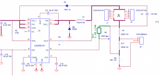
Due thte unavailabily of the TPS92151 we are trying to cope this situation installing a 5 turn trimmer in parallel to the sensing resistor in order to pick up a portion of voltage and send it (via trimmer brush) to the CS pin. In this way we are trying to adjust  case by case the LED current. We experimented many damages to the chip, even without any activity on the trimmer.

Where is the problem? PCB layout was not so compact and the trac between trimmer and CS pin is  going around some component in a way I do not like...

Is somebody able to give us some suggestion?

Roberto

  • It is not clear exactly how your implementation looks but you should keep in mind that CS pin abs max is 7V and that you do not exceed it.

  • We just provided a potentiometer 5 turns 100 ohm  in parallel to the R SENS in order to send to CS  a variable portion of the voltage across R SENS trhough the potentiometer brush.

    Just to avoid some potential discontinuity during the adjustemt of the potentiometer we added a 2k2 resistor (gree lines ) but it did not solve the issue.

  • This is going to be difficult to debug. Can you make sure that you are no violating any abs max conditions on any pin by probing?

    Secondly, what is the total specification of your project? Is your input voltage <36V and >5V? If so, we have a new device about to be launched in a couple of weeks which has an analog adjust pin similar to TPS92515 which you were previously using. Perhaps that would be a better choice for you. It is also synchronous with all FETs integrated. I cannot share all details on the public forum right now, but it will be publicly visible by May 2022 on ti.com