This thread has been locked.

If you have a related question, please click the "Ask a related question" button in the top right corner. The newly created question will be automatically linked to this question.

TPS5420-Q1: Output Inductor and capacitor.

Part Number: TPS5420-Q1
Other Parts Discussed in Thread: TPS5420, , TPS5410-Q1, TPS5410

Hi,

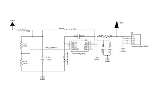
   To reduce the size of our PCB we changed our output inductor and capacitor. The part number of inductor and capacitor is given below. 

  1. O/p Inductor - XAL5050-223MLC              - 22uH, 3.4 Irms @40deg
  2. I/p Capacitor - GRT21BC71E106KE13L    - 10uF, 0805,X7S, 25V
  3. I/p Capacitor - GRM21BR61H475KE51L   - 4.7uF, 0805, X5R, 50V
  • Input Voltage  - 28V DC.
  • Output Voltage - 15V DC.

Issue : The above is our design specifications. In this above design we have a problem with this regulator while switching on TPS5420 drawing more current and IC is going bad. so kindly clarify the issues.

Thanks 

Saravanakumar D

  • Hello,

    Your diode appears to be connected to BOOT instead of PH. If this is indeed the case, please connect the diode from PH to GND and try to power on the device. 

    Regards,

    Harrison Overturf 

  • Thanks  for you reply Harri

    Sorry i forget to inform you that .....we did that changes before but still we are facing the same issue.....

    any other changes required ?

    Regards 

    Saravanakumar D 

  • Hello,

    Thanks for the clarification, can you share an updated schematic please?

    What is your expected load current?

    Are you experiencing IC failure at start up or does this happen after the part has been running for some time? 

    Have you captured any scope photos when the IC goes bad? 

    The maximum input voltage to the device is 40V and it looks like you are operating at 36Vin. Is there any input protection to ensure the absolute maximum rating is not being violated?

    Regards,

    Harrison Overturf 

  • 1. Thanks for the clarification, can you share an updated schematic please?

                           -- Yes, I am attaching the Schematics

    2. What is your expected load current?

                          -- As of now our load current will 100mA maximum

    3. Are you experiencing IC failure at start up or does this happen after the part has been running for some time? 

                         -- We are experiencing the failure at start up. Immediate after powering ON.

    4. Have you captured any scope photos when the IC goes bad?

                          -- No, IC burnt immediate after powering ON. 

    5. The maximum input voltage to the device is 40V and it looks like you are operating at 36Vin. Is there any input protection to ensure the absolute maximum rating is not being violated?

                            -- As per the electrical characteristics input voltage is 5.5 to 36V our input voltage is 28V as i mentioned above.

                            -- No input protection is given. 

    FYI : We have changed the inductor MSS5131-683MLC(1.1 Irms),XAL5050-223MEC (3.4 Irms)

    Regards

    Saravanakumar D 

  • Sch_TI.pdf

    Attaching the updated schematics.......

  • Hello Saravanakumar,

    Thanks for your answers and sharing the schematic, I understand you swapped the inductor to XAL5050-223MEC (3.4 Irms).

    The schematic shows TPS5410-Q1 instead of TPS5420-Q1, please confirm which is being used. 

    If the part is being damaged at start up that leads me to believe that there could be some sort of overvoltage condition occurring. Are there long leads connecting from the 28P0V power supply to the input to the buck? Long leads and fast input slew rates can produce voltage spikes at the input that could exceed the absolute maximum rating of the device. Can you try powering on the TPS5410 starting from a low voltage (0V) and slowly ramp the input voltage up to 28V? 

    Also is U2 the only device being damaged or is U5 damaged as well? 

    Regards,

    Harrison Overturf 

  • Hey Harri,

     Thanks for your reply.

    The schematic shows TPS5410-Q1 instead of TPS5420-Q1, please confirm which is being used. 

           -- Actually we designed for TPS5410-Q1 because of the chip shortage currently we are using  TPS5420-Q1.

    If the part is being damaged at start up that leads me to believe that there could be some sort of overvoltage condition occurring. Are there long leads connecting from the 28P0V power supply to the input to the buck? Long leads and fast input slew rates can produce voltage spikes at the input that could exceed the absolute maximum rating of the device. Can you try powering on the TPS5410 starting from a low voltage (0V) and slowly ramp the input voltage up to 28V? 

         -- Okay I will try this and update you.

    Also is U2 the only device being damaged or is U5 damaged as well? 

          -- Yes only U2 the only device is getting damaged.

    Query :

    1. If i reduced TPS5420-Q1 input voltage Vin to 15V  and the Vout is 12V will it solve this issue.
    2. Will it affect by changing the input and output capacitor and output inductor?. Kindly suggest will it be a root cause for this issue. Will inductor and capacitor size and value place a role?
    3. As per your suggestion if i connect my buck input less than 15V and is it possible to get my expecting Vout  as 15V.

    Regards

    Saravanakumar D 

  • Hi Saravanakumar,

    You can try to reduce the input voltage to 15V and see if the problem persists with that input voltage. Since we don't exactly know what is causing the device damage yet I can't comment whether changing the input and output capacitor values will change anything. Based on the values given in the schematic these components looks acceptable. 

    You will not be able to get 15V output for 15V input, the output will be some value smaller than 15V due to conduction losses. 

    Please try slowly increasing the input voltage from 0V to your desired 28V and let me know the results. 

    Also do you have a PCB layout that you can share with me so I can review? 

    Regards,

    Harrison Overturf 

  • Hey harri,

    Is it possible to get your official mail Id 

    Regards

    Saravanakumar D 

  • One of the same design PCB was working by changing the inductor size and value to(MSS1260-333MLC - 2.7Irms). That's the reason i asked whether the change of inductor or capacitor will be the cause of this problem.

    Regards

    Saravanakumar D

  • Hi Saravanakumar,

    Here is my email: h-overturf@ti.com 

    I double checked your output capacitor value and realized that it will not provide enough capacitance with the 15V output voltage applied across it. See the Dc Bias Characteristics here: GRT21BC71E106KE13(GRT21BC71E106KE13L,GRT21BC71E106KE13K)|Ceramic Capacitors(SMD)|Ceramic Capacitors|Capacitors|Murata Manufacturing Co., Ltd.

    Can you try increasing the output capacitance and see if that helps? 

    I'll close this thread and we can continue the conversation via email. 

    Regards,

    Harrison Overturf 

  • Okay Harri....

    Thank you !!!

  • You're welcome.

    Regards,

    Harrison Overturf