This thread has been locked.

If you have a related question, please click the "Ask a related question" button in the top right corner. The newly created question will be automatically linked to this question.

Question with TPS5420

Other Parts Discussed in Thread: TPS5420

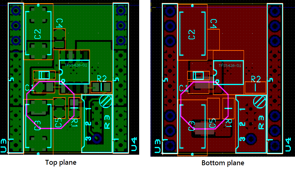
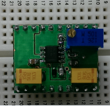
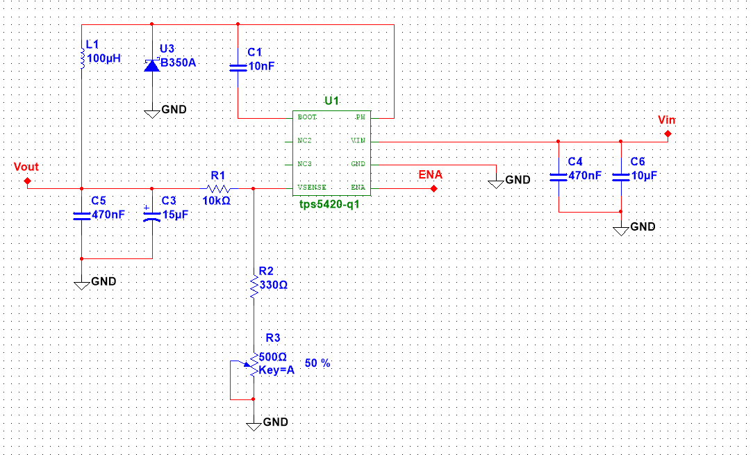
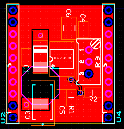
Hello, I have a problem when using the TPS5420. I want to convert the 28V to 15V and 24V. Using the different ration of R1 and R2 to reach the goal. Here is the schematic of the test board. Resistor R1 is 10k ohm. Resistor R2 is constructed by 470 ohm and a potentiometer of 500 ohm(R2 and R3 in schematic snapshot). And the enable pin is floating.

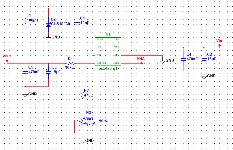
I can adjust the potentiometer to get 15V and 24V output. And I use an dc electric loads(Agilent N3300A) to force the output current. I can force the output current 1A when testing 24V output.(1A is the limit of power supply)

But there is a problem when i test 15V output. When i force the output current 1A, the tps5420 will fail. The input output and ground are shorting.I have no idea about this problem.  

Please let me how to solve this problem and why this happen. 

Thanks a lot.

  • Hello,

    Can you clarify if this is a modeling question or a question about the working of the device? If it is related to the working of the device, I will move this to the non isolated DC DC forum. If it is related to simulations, can you provide more details of your simulation environment and possibly share your simulation files.

    Thanks,
  • Hello,

    I'm so sorry about that. The question is about the working of the device. I didn't notice the classification. Please move this to the non isolated DC DC forum.

    Thanks a lot.
  • Can you tell me about the input and output capacitors? TPS5420 requires high quality ceramic input capacitor located close to the IC VIN and GND pins. The output capacitor must have a well placed ESR zero to interact with the internal compensation. After we verify teh component values we can dig deeper. How many circuits are showing this behavior out of how many total?
  • Hi John,

    I used the same configuration of input and output capacitors.Input capacitors are C2 and C4 in the snapshot. Output capacitors are C3 and C5 in the snapshot.

    C2 and C3 are the same. The capacitor is manufactured by KEMET. The capacitance is 15 uF. The manufacture part number is T495X156K050ATE300.

    C4 and C5 are the same.The capacitor is manufactured by AVX. The capacitance is 0.47 uF. The manufacture part number is 08051C474KAT2A.

    I will provide any information if you need.

    I'm so sorry that i can't understand the sentence. "How many circuits are showing this behavior out of how many total?". My English ability is not good enough. Please rewrite the sentence in other simple way. I will provide the information as soon as possible.

    Thank your for replying.

    Thank you very much.
  • You have built how many circuits in total? Of that total amount, how many are showing this problem? You will probably need a ceramic X5R or X7R input capacitor. Something in the range of 10uF. I will check the suitability of your output cap. I would also like to have a look at your PCB layout.
  • I checked the output filter. That capacitor should be acceptable for Cout. So if you can first try replacing the input capacitor. Let me know if that fixes your issue.
  • Hi John,

    I made two test boards first. One is used to output 15V, the onther is used to output 24V. First, i input a 30V voltage(want to output more current). When i forced the output current is 1A, the 15V-output and the 24V-output test boards all showed this problem. So i checked the datasheet, i found the diode can't meet the requirement.(Reverse voltage must be higher than the VINMAX + 0.5V).At that time, i thought that the diode failed. But i changed the diode, the problem was still shown.

    So i made a new test board that can output 15V and 24V by adjusting the potentiometer. At this time, i fixed the input volatge 28V. I adjusted the potentiometer to output 24V in 1A. After 30 minutes, the output is normal(23.707V 1.103A). So i adjusted the potentiometer to output 15V. When i forced the output current is 0.75A, the performance is pretty good(14.873V 0.753A). But i forced the output  current 1A, the problem showed.

    I only have a 10uF MLCC. The manufacture number is C0805C106K4PACTU. The capacitor is manufactured by KEMET. But the voltage rate is 16V. I don't sure the capacitor is suitable. If that is suitable, should i replace the C2 in the snapshot with this capacitor? If that is not suitable, please suggest a good one.

    There are the layout and end product snapshots. The dimension is 20.32 x 25.40 mm. If there are any bad design, please tell me how to improve it.

    Thank you for patiently replying.

    Thank you very much.

  • For the input capacitor, you can select one of these:

    http://www.digikey.com/product-search/en?pv13=69&pv14=22&pv17=19&FV=fff40002%2Cfff8000b&mnonly=0&newproducts=0&ColumnSort=0&page=1&quantity=0&ptm=0&fid=0&pageSize=25

    For the layout you need to connect C2 and Cr directly across the VIN and GND pins.  It looks like your top side grounding is not well routed.  You can look here for some guidance on the layout.

    No problem with mounting the inductor on the backside if you want to save space.  For the short term, once you locate a proper input capacitor, you can hand modify the board to loacte the 10uF directly across teh VIN and GND pins.  Then we can look at some waveforms if you still have problems.

  • Thank your for your suggestion.

    I'll buy a suitable capacitor and replace it. Do you mean that i need to connect input capacitor directly across the VIN and GND pins?(Cr -> C4?) Don't connect them through the via.

    I'll tell you if that works after replacing input capacitor and modify the layout.

    Thank you very much.
  • Yes hand connect the 10 uF so it is directly across VIN and GND pins.  You can leave the small cap where it is for now.  LMK if this fixes your issue.

  • hi John,

    I had changed my schematic and layout. Here are the snapshots. Please help me verifying  them.

    In the schematic, I changed the input capacitor and diode.

    The new capacitor is 10uF, manufactured by Kemet, manufactured number is C1210C106K5RACTU.

    The new diode's peak reverse voltage is 50V, manufactured by Diodes.Inc, manufactured number is B350A.


    The green one is top layer.  The red one is bottom layer.

    If the layout is ok, I will make a test board.

    I'll tell you  that if there still have the problem.

    Thank you very much.

    Happy new year.